Angle of Arrival Measurements Using RF Carrier Synchronization and Phase Alignment Methods

a technology of rf carrier and angle of arrival, applied in the direction of synchronisation arrangement, baseband system details, instruments, etc., can solve the problems of delay measurement of phase measurements, ineffective method, and high cost of the overall system,

Active Publication Date: 2017-08-10
PHASORLAB
View PDF6 Cites 29 Cited by
  • Summary
  • Abstract
  • Description
  • Claims
  • Application Information

AI Technical Summary

Benefits of technology

[0005]Described in this document are multiple ways to obtain angle of arrival (AOA) measurements for use in wireless communications and other applications such as positioning. We describe how angle of arrival (AOA) can be extracted utilizing high-precision carrier offset and initial phase offset estimation methods, resulting in an economical way of sensing arriving angle of an RF signal at a set of antennas. In addition, by making use of our high-precision carrier synchronization technology we present an additional method of sensing arriving angle of RF signals by comparing RF signals ...

Problems solved by technology

This is an important advantage over the traditional method of having to detect the arriving signals simultaneously at an array of antennas, which causes the overall system to be too expensive or too bulky to be practical for many potential applications such as mobile positioning systems.
Phase measurements may be delay measurements.
Therefore, as can be seen in equation (3.23), when the two nodes are not synchronized in frequency, the resulting calculation can easily be dominated by this process delay time, D.sub.B, which makes this method ineffective.
Antenna array here co...

Method used


Image

  • Angle of Arrival Measurements Using RF Carrier Synchronization and Phase Alignment Methods
  • Angle of Arrival Measurements Using RF Carrier Synchronization and Phase Alignment Methods
  • Angle of Arrival Measurements Using RF Carrier Synchronization and Phase Alignment Methods

Examples


Embodiment Construction

[0040]The present disclosure takes advantage of the methods of achieving highly accurate RF Carrier Synchronization and Phase Alignment as described in U.S. Pat. Nos. 9,048,979 and 9,048,980. Our disclosed methods utilize statistical nature of random quadrature modulated signal in order to accurately measure frequency offset and initial phase offset in the received carrier signal.

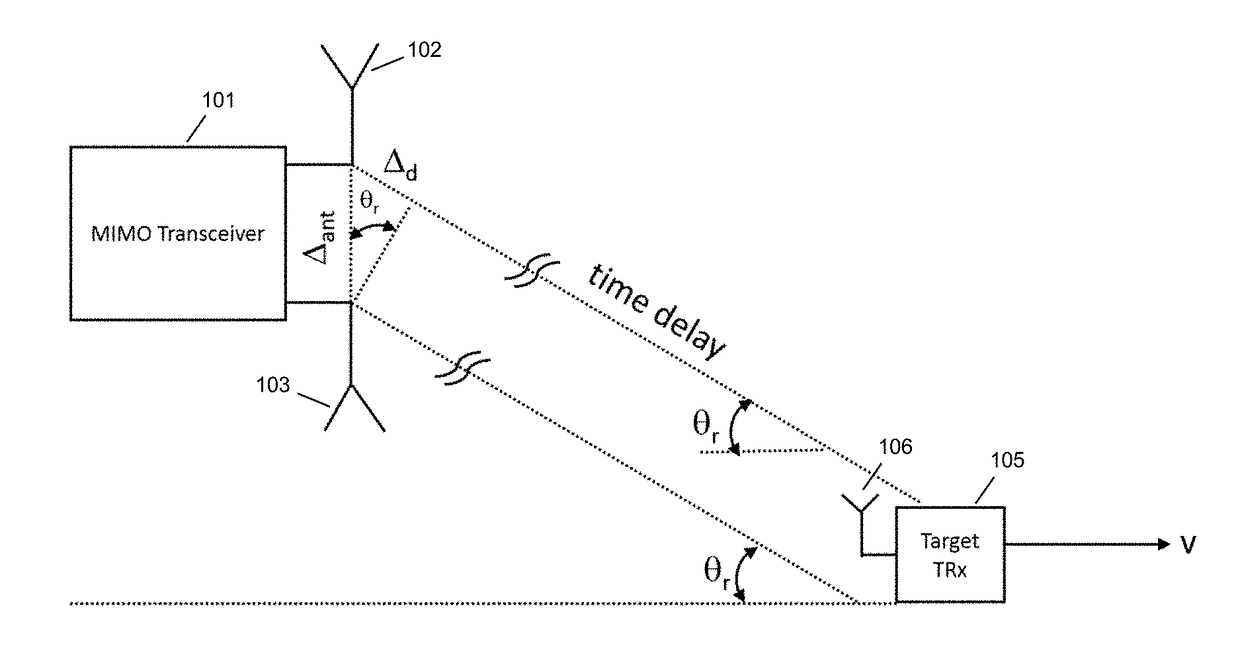
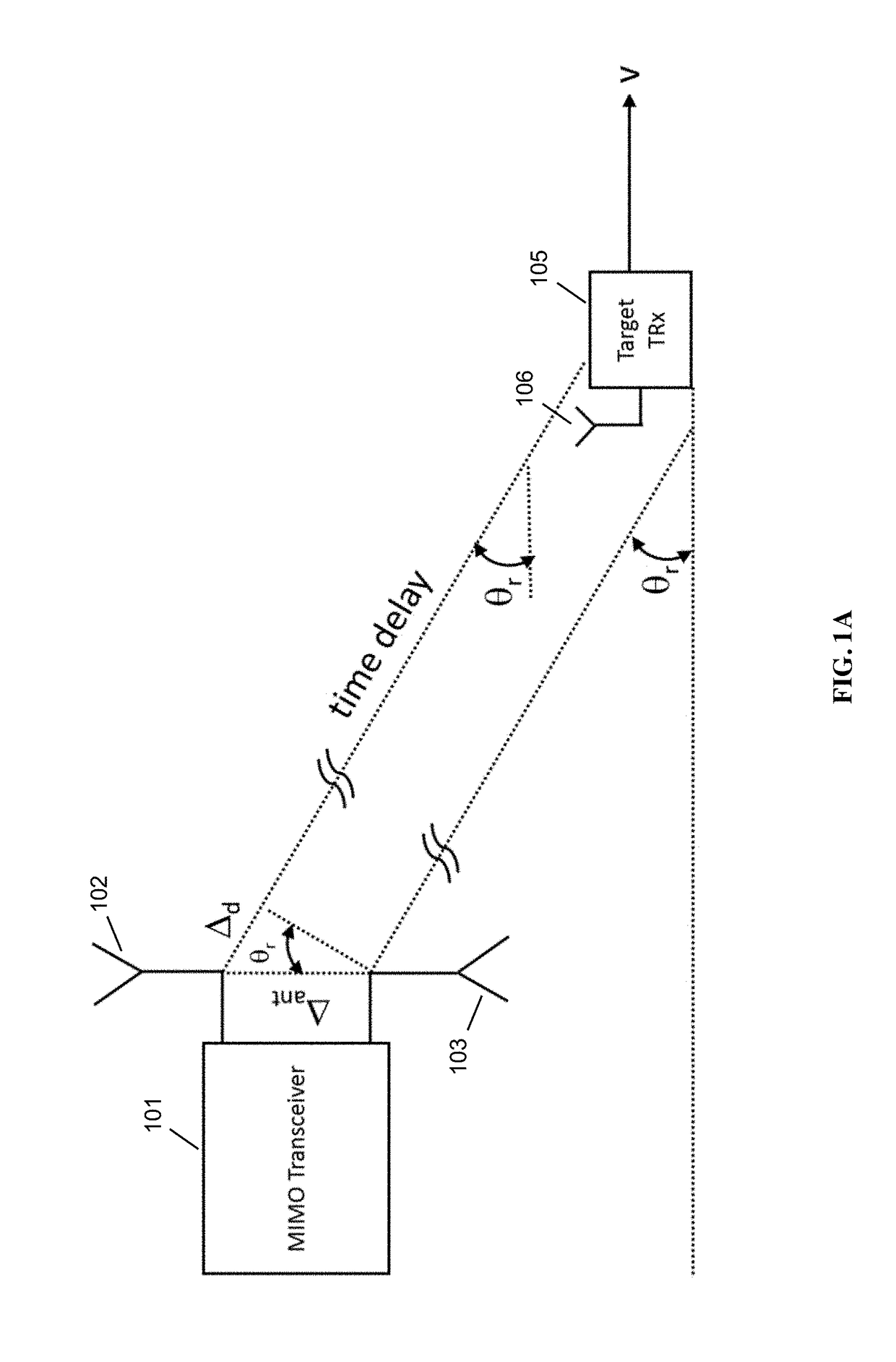
[0041]Our method of measuring angle of arrival uses standard widely available commercial off the shelf radio equipment and supports different antenna configurations.

[0042]See U.S. Pat. No. 9,048,980 and the other documents referred to herein (each hereby incorporated by reference in their entirety) for a detailed description of the RF Carrier Synchronization and Phase Alignment Methods that allows a highly accurate carrier frequency offset measurement in the order of 1 ppb or better and initial phase offset measurement in the order of 0.1 degrees or better. Also in these documents is a description of a freq...


PUM


Abstract

A method for determining an angle of arrival (AOA) of a received signal is disclosed, comprising: generating a baseband information signal by mixing a received signal with a local oscillator (LO) signal, the received signal being an in-phase signal and quadrature signal uncorrelated with each other and derived from different input data sets; obtaining baseband signal samples of the baseband information signal having an in-phase signal sample and a quadrature signal sample; determining a transmitter phase offset based on an estimated correlation between the in-phase signal samples and the quadrature signal samples; performing a plurality of phase measurements using a plurality of antennas to obtain a plurality of phase measurements; correcting the plurality of phase measurements based on the transmitter phase offset to produce a plurality of corrected phase measurement; and calculating an AOA of the received signal based on the difference between the plurality of corrected phase measurements.

Description

CROSS-REFERENCE TO RELATED APPLICATIONS[0001]This application claims the benefit of priority under 35 U.S.C. §119(e) of U.S. Provisional Patent Application No. 62 / 326,091, filed Apr. 22, 2016 and titled “High-Resolution High-Dynamic Range Angle of Arrival (AOA) Measurements Using Super Synchronized Wireless Network,” and is also a continuation-in-part under 35 U.S.C. §120 of, and claims priority to, U.S. patent application Ser. No. 14 / 727,859, filed Jun. 1, 2015 and titled “RF Carrier Synchronization and Phase Alignment Methods and Systems,” which itself is a continuation of, and claims priority to, U.S. patent application Ser. No. 14 / 043,789, filed Oct. 1, 2013 and also titled “RF Carrier Synchronization and Phase Alignment Methods and Systems,” each of which is hereby incorporated by reference in its entirety for all purposes. Priority is not claimed by this application to U.S. Provisional Patent Application 61 / 708,116. Additionally, U.S. Pat. Nos. 9,048,979, 9,048,980, and U.S. P...

Claims


Application Information

Patent Timeline
IPC IPC(8): G01S3/48H04L7/00
CPCG01S3/48H04B7/0413H04L7/0016G01S3/18G01S3/46H04B7/0617H04B7/0802H04B7/086H04B7/10H04L27/0014H04W56/0035H04L2027/003H04L2027/0046H04L2027/0053H04L2027/0067H04L25/02
Inventor PARK, JOSHUA C.DEMIRDAG, CUNEYTWOLVERTON, GLENTOPIWALA, DEVANGMCFARTHING, PAUL
Owner PHASORLAB
Why Eureka
Try Eureka