Lacrosse head

a head and lacrosse technology, applied in the field of lacrosse, can solve the problems of reducing the scooping efficiency, wear and tear of the exposed pocket strings, and inefficient and somewhat obstructive design, and achieve the effects of constant cross-section, easy moldability, and smooth ground ball play

Active Publication Date: 2017-08-17
WM T BURNETT IP
View PDF9 Cites 8 Cited by
  • Summary
  • Abstract
  • Description
  • Claims
  • Application Information

AI Technical Summary

Benefits of technology

[0009]It is, therefore, an object of the present invention to provide a lacrosse stick head having a front scoop geometry optimized to promote smooth ground ball play such as scooping of a ball off of a playing surface.
[0010]It is also an object of the present invention to provide a lacrosse head having an optimized front scoop geometry as described above that extends over a significant portion of the scoop width, thereby protecting pocket stringing that extends through the scoop.
[0011]It is another object to provide a lacrosse head having an optimized front scoop geometry as above that is easily moldable and ultimately durable and robust.
[0012]The present invention is a lacrosse head having a distal scoop with a substantially constant cross-section along at least an inch, located one-half inch on either side of the front dead center of the scoop portion of the lacrosse head centered at its foremost center-point (e.g., A-A′ of FIG. 1). The term “substantially constant cross-section” is herein defined as not deviating from the cross-section's basic shape and maintaining reasonable proportionality of the fundamental characteristics of that shape as described in the point framework defined below. Referring back to FIG. 5 (inset), the features of the present cross-section likewise resemble a knife blade, and the analogy is helpful in defining the relevant points. There is likewise a tip or “foremost point” (FP)”, a spine (back edge of the blade), a tang embedded in the handle, the tang extending along a “rear edge” (RE) to a rearmost corner point (RCP). The blade edge runs from tip to a heel, and there is a recessed choil behind the heel arching inward. There is a “low continuous carve point” (LCP) where the heel joins the choil, the choil arching inward to a “rear-innermost point” (RI), all said points being connected by a continuous perimeter. The choil indentation at the heel in one preferred embodiment defines a U-shaped cavity and in another embodiment an angled notch, in either case the cavity or notch extending toward said foremost point (FP). In one embodiment, the perimeter section joining said foremost point (FP) and low continuous curve point (LCP) is a smooth continuous outwardly-convex curve. In another embodiment, the perimeter section joining said foremost point (FP) and low continuous curve point (LCP) is a relatively straight line. In yet another embodiment, when the lacrosse head is horizontally-oriented along the x-axis of an xyz coordinate system as shown in FIG. 10, the low continuous curve point (LCP) projects below the rearmost corner point (RCP), the rear innermost point (RI), and any point there between along the rear edge (RE). The improved scoop geometry is optimized to promote smooth ground ball play and to eliminate scoop string wear from playing surface contact.

Problems solved by technology

This geometry is used primarily to achieve durability at a highly stressed portion of a lacrosse head, while also facilitating conventional clam shell mold manufacturing.+ However, it results in an inefficient and somewhat obstructive design for an essential lacrosse head maneuver, i.e., scooping, Scooping a lacrosse ball resembles a snow shoveling motion where the front and bottom side of the scoop 112 scrape the playing surface in an effort to entrap a ball that is resting or rolling on the playing surface.
The jagged or angled geometry (FIG. 4) of the prior art scoop cross-sections makes for a less than smooth head / surface interaction, decreasing scooping efficiency.
In addition, the conventional scoop cross-section is not configured to prevent exposed strings, leading to wear and tear of the exposed pocket strings S as seen in (FIG. 5).
The strings S and playing surface (dotted lines) interact directly during play as seen in FIG. 5, resulting in substantial abrasion and wear.

Method used


Image

  • Lacrosse head
  • Lacrosse head
  • Lacrosse head

Examples


Embodiment Construction

[0026]The present invention is a molded double-wall synthetic lacrosse head having an improved scoop geometry that facilitates scooping up a ball while it rests or rolls on the playing surface.

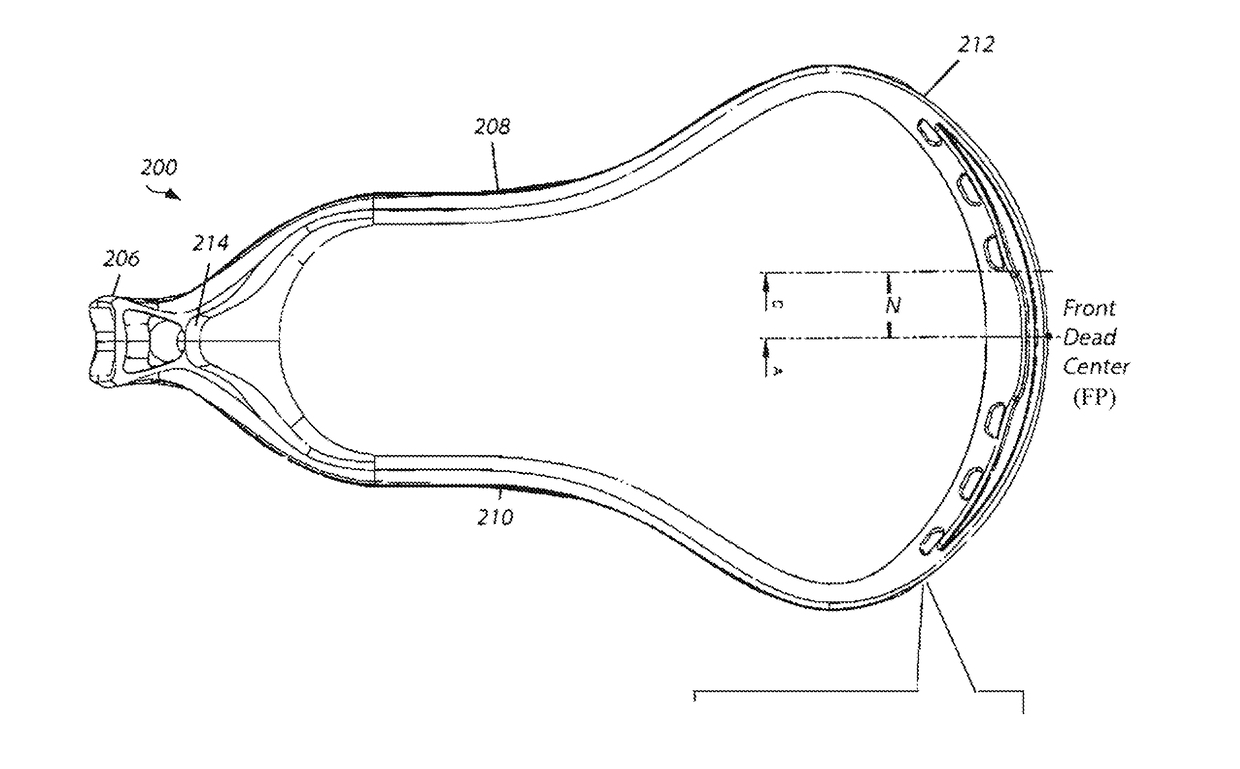
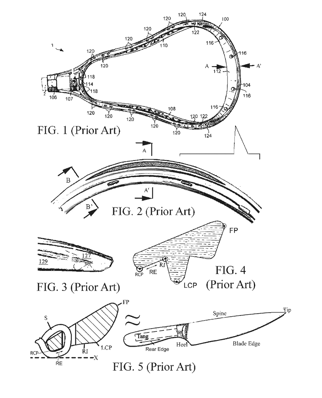
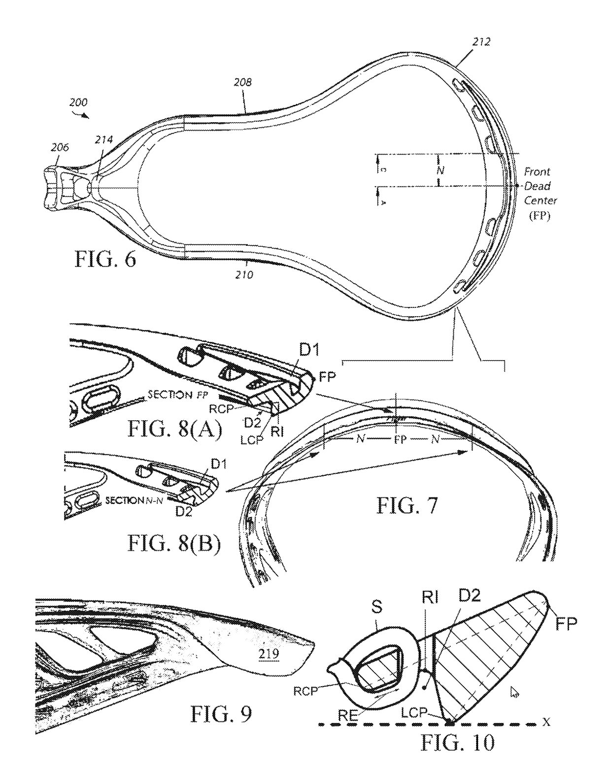
[0027]For purposes of this disclosure, the lacrosse head “front dead center” is herein defined as the foremost point (FP) on the lacrosse head that is furthest along the x-axis from the origin when the lacrosse head is horizontally-oriented along the x-axis of an xyz coordinate system. FIGS. 6-9 illustrate the lacrosse head with improved scoop geometry for ground play according to the invention, which improved scoop geometry is described with reference to a cross-section taken at front dead center along the x-y plane.

[0028]As seen in FIG. 6 the lacrosse head 200 generally comprises a V- or U-shaped frame engaged to a handle at a juncture 206. A stop member 214 is provided adjacent to the juncture 206 and a pair of sidewalls 208 and 210 extend from the stop member 214 and juncture 206 in a gene...


PUM


Abstract

A lacrosse head having a front scoop geometry optimized to promote smooth ground ball play such as scooping of a ball by ground contact. The lacrosse head has a distal scoop with a mid-section cross-section shaped like a chef's-knife with a foremost point, a rear edge (lower edge of tang), a rearmost corner point (tower distal end of tang), a low continuous curve point (where heel joins choil), and rear-innermost point (choil), with a continuous perimeter bounding all of said points, the perimeter bounding said rear edge, lowest continuous curve point, and rear-innermost point defining a cavity extending toward said foremost point. The perimeter joining the foremost point and low continuous curve point is formed to optimize ground ball play when incorporated into a lacrosse head scoop,

Description

CROSS-REFERENCE TO RELATED APPLICATIONS[0001]The present application derives priority from U.S. Provisional Patent Application No. 62 / 294,016 filed 11 Feb. 2016.BACKGROUND OF THE INVENTION[0002]1. Field of the Invention[0003]The present invention relates to lacrosse and, more particularly, to an improved head for a lacrosse stick adapted for improved playing characteristics.[0004]2. Description of the Background[0005]In 1970, the introduction of double-wall, synthetic lacrosse heads revolutionized the game of lacrosse. In comparison to the traditional single-wall heads made of wood, the molded synthetic heads imparted a lightness, maneuverability, and flexibility never-before experienced by lacrosse players. These performance advantages greatly enhanced players' skills such as throwing, catching, cradling, and scooping, and brought the sport of lacrosse to new levels of speed and excitement.[0006]FIG. 1 illustrates a typical molded double-wall synthetic head 104 mounted on a handle ...

Claims


Application Information

Patent Timeline
Patent Type & Authority Applications(United States)
IPC IPC(8): A63B59/20
CPCA63B59/20A63B60/52A63B2102/14
Inventor BROWN, AUSTIN
Owner WM T BURNETT IP
Why Eureka
Try Eureka