Superconducting Current Pump

Active Publication Date: 2017-08-17
VICTORIA LINK LTD +7
View PDF1 Cites 12 Cited by
  • Summary
  • Abstract
  • Description
  • Claims
  • Application Information

AI Technical Summary

Benefits of technology

[0045]Generally, the absence of moving parts within the cryogenic enclosure removes the general requirement for extremely high reliability of moving parts within the cryostat. Di

Problems solved by technology

Such current leads are a significant source of heat load upon the cryogenic environment due to both heat conduction along, and ohmic dissipation within, the current leads, which are operated at high currents.
In addition, the accompanying electrical current source and high current cables have a large footprint, are not easily portable, and are

Method used


Image

  • Superconducting Current Pump
  • Superconducting Current Pump
  • Superconducting Current Pump

Examples


Embodiment Construction

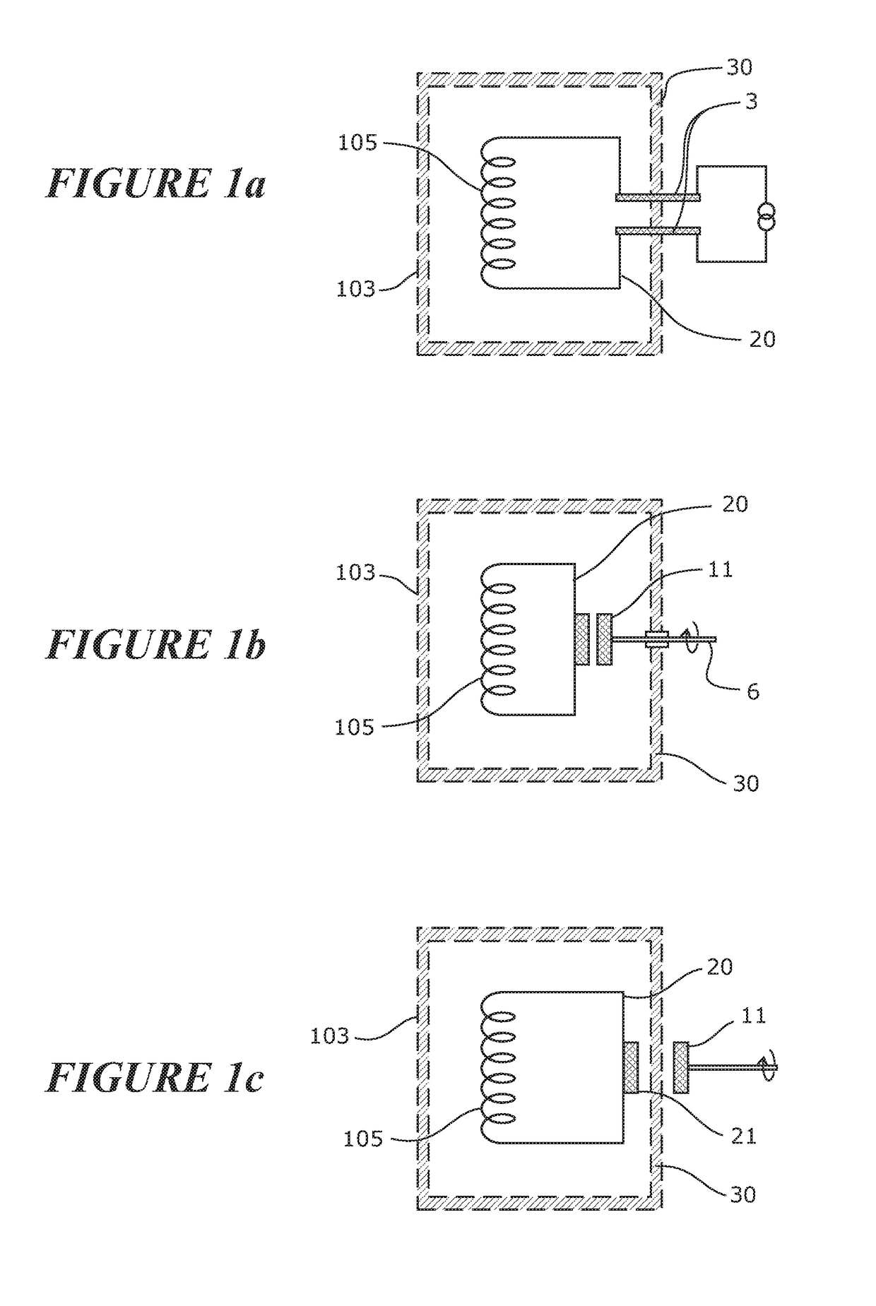
[0076]FIG. 1a schematically shows a prior art superconducting circuit 20 comprising an electromagnetic coil 105 which is contained within a cryostat 103. In operation the cryostat 103 comprising thermally insulating walls 30 maintains an internal temperature at or below the superconducting transition temperature of the superconducting elements within the superconducting circuit. The superconducting circuit 20 is energised using an external current source which injects current into the circuit by using normally conducting current leads 3 which penetrate the cryostat wall 30.

[0077]FIG. 1b schematically shows another prior art superconducting circuit 20 comprising an electromagnetic coil 105 which is contained within a cryostat 103. The superconducting circuit 20 is energised using a rotating flux pump comprising a rotor 11 located within the cryostat enclosure 103. A drive shaft 6 to the rotor 11 penetrates the cryostat wall 30.

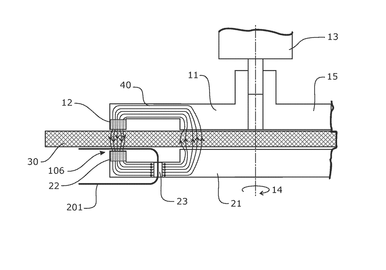
[0078]FIG. 1c schematically shows a superconducting circu...


PUM


Abstract

A superconducting current pump arranged to cause a DC electrical current to flow through a superconducting circuit accommodated within a cryogenic enclosure of a cryostat comprises a rotor external to the cryogenic enclosure and a stator within the cryogenic enclosure, the rotor and stator separated by a gap through which passes a thermally insulating wall of the cryogenic enclosure, the rotor and the stator comprising at least in part a ferromagnetic material to concentrate magnetic flux in a magnetic circuit across the gap between the rotor and the stator and through the wall, so that movement of the rotor external to the cryogenic enclosure relative to the stator within the cryogenic enclosure induces a DC transport current to flow around the superconducting circuit within the cryogenic enclosure. There is no coupling between a drive motor external to the cryogenic enclosure and an internal rotor which may introduce a path for heat leakage into the cryostat, in turn increasing the heat load and thus increasing the cooling power required to maintain the cold components within the cryogenic enclosure at the low operating temperature required.

Description

FIELD OF THE INVENTION[0001]The invention relates to a superconducting current pump for energizing a superconducting circuit.BACKGROUND[0002]The commercial production and application of high temperature superconducting (HTS) wire is well established. High temperature superconductor materials are type II superconductors with a high superconducting transition temperature (Tc), typically such that Tc>77K. Electromagnetic coils wound from HTS wire can achieve high magnetic fields due to the extremely low-levels of heat dissipation at high current densities when operated at temperatures below Tc. In order to maintain the temperature below Tc it is necessary to contain the superconducting coil within a cryostat that is coupled to a cooling source. Electrical current is usually supplied to an HTS superconducting circuit via an electrical circuit which includes current leads made from a normal conducting metal. These current leads penetrate the cryostat wall to link the superconducting c...

Claims


Application Information

Patent Timeline
IPC IPC(8): H01F6/00H01F6/04H02K1/27F17C3/08H02K55/00H02P7/00H02K9/19H01F6/06H02K1/12
CPCH01F6/006H01F6/06H01F6/04H02K1/2786F17C3/085H02K55/00H02P7/00H02K9/19H02K1/12H02K1/2791G01R33/3815H01F6/008H01F13/00H10N60/84H01F6/005
Inventor WALSH, ROWAN MARTINBUMBY, CHRISTOPHER WILLIAMBADCOCK, RODNEY ALANSLADE, ROBERT ANDREWJIANG, ZHENANHAMILTON, KENT ANTHONYFEE, MICHAEL GRAEME
Owner VICTORIA LINK LTD
Why Eureka
Try Eureka