
Swallow exerciser

a technology of geolocation information and exerciser, which is applied in the direction of receiving system details, receiving monitoring, baseband system details, etc., can solve the problems of difficult aiming of antennas, the inability to achieve optimum reception of receiving antennas, and the inability to quickly lose digital signal reception

Active Publication Date: 2017-08-17
UNIV OF SOUTHERN CALIFORNIA +1
View PDF6 Cites 5 Cited by
  • Summary
  • Abstract
  • Description
  • Claims
  • Application Information

AI Technical Summary

Benefits of technology

The patent text describes a method and device for aligning an antenna to receive signals from a transmitting antenna. The receiving antenna receives geolocation information of both the receiving and transmitting antennas and initiates an auto-programming sequence to tune to the channels received from the transmitting antenna. The signal processor calculates a signal path based on the geolocation information and programmed channels. The receiving antenna can select one of the transmitted signals and align itself to tune the selected signal. The method and device allow for quick and efficient alignment of the receiving antenna to the transmitting antenna.

Problems solved by technology

However, digital signal data is either perfect or non-existent at the receiving end, which implies the possibility of a sudden loss of digital signal reception known as the “cliff effect.” Antennas can be difficult to aim when outputting digital signals because of the cliff effect and because of delays in decoding and displaying the signal.
Aligning the receiving antenna for optimum reception may require complex manual alignment.
However, this method is often difficult for an inexperienced user.
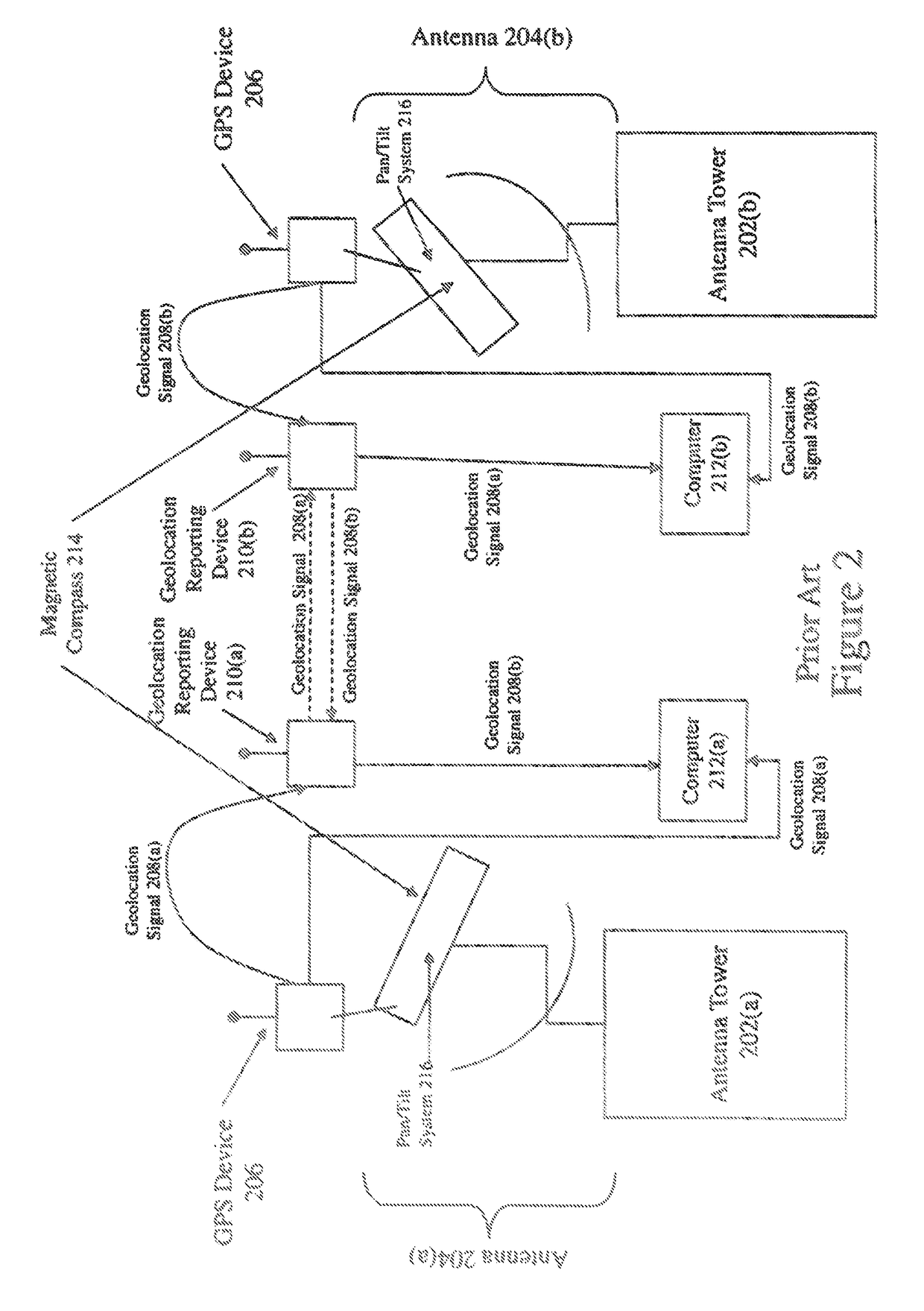
However, though the output of a smart antenna may include a pointing direction as determined by geolocation information sent to external devices such as computers, these smart antennas are not able to communicate geolocation information directly to each other.
Thus, the ability to reject channel interference from an interfering station is often limited.
This results in a noisy signal and poor reception of the signal by the receiving antenna 304.

Method used


Image

  • Swallow exerciser
  • Swallow exerciser
  • Swallow exerciser

Examples


Embodiment Construction

[0027]The exemplifications set out herein illustrate preferred embodiments of the invention, and such exemplifications are not to be construed as limiting the scope of the invention in any manner.

[0028]The invention relates to a method and apparatus for optimizing the alignment of a directional receiving antenna such as a television signal receiver. The invention uses geolocation of a transmitting antenna and the directional receiving antenna to determine an optimum alignment for the directional receiving antenna. After the optimum alignment is determined, the directional receiving antenna may be aligned electronically and / or mechanically or instructions for aligning the antenna correctly may be provided to a user.

[0029]A transmitter sends its geolocation information, e.g. latitude and longitude, to a receiver. The location information may be acquired using any location finder technology such as GPS. Geolocation information of a receiver antenna may also be sent to a transmitter ant...


PUM


Abstract

A method and system for antenna alignment is provided at a receiving antenna. Geolocation information of the receiving antenna is entered. An auto-programming sequence is initiated to tune to channels received from a transmitting antenna. A plurality of transmitted signals is received from the transmitting antenna. Each of the plurality of transmitted signals is transmitted on a respective channel and includes geolocation information of the transmitting antenna, conditional access data, and a payload. A signal processor of the receiving antenna calculates a signal path between the receiving antenna and the transmitting antenna for receiving each of the plurality of transmitted signals based on the geolocation information of the receiving antenna and the geolocation information of the transmitting antenna. A storage device of the receiving antenna records, as part of a selection list, a channel number and the calculated signal path to the transmitting antenna for each of the plurality of transmitted signals. One of said plurality of transmitted signals is selected. The receiving antenna is aligned, using a pan / tilt system, to tune the selected one of the plurality of transmitted signals according to the calculated signal path.

Description

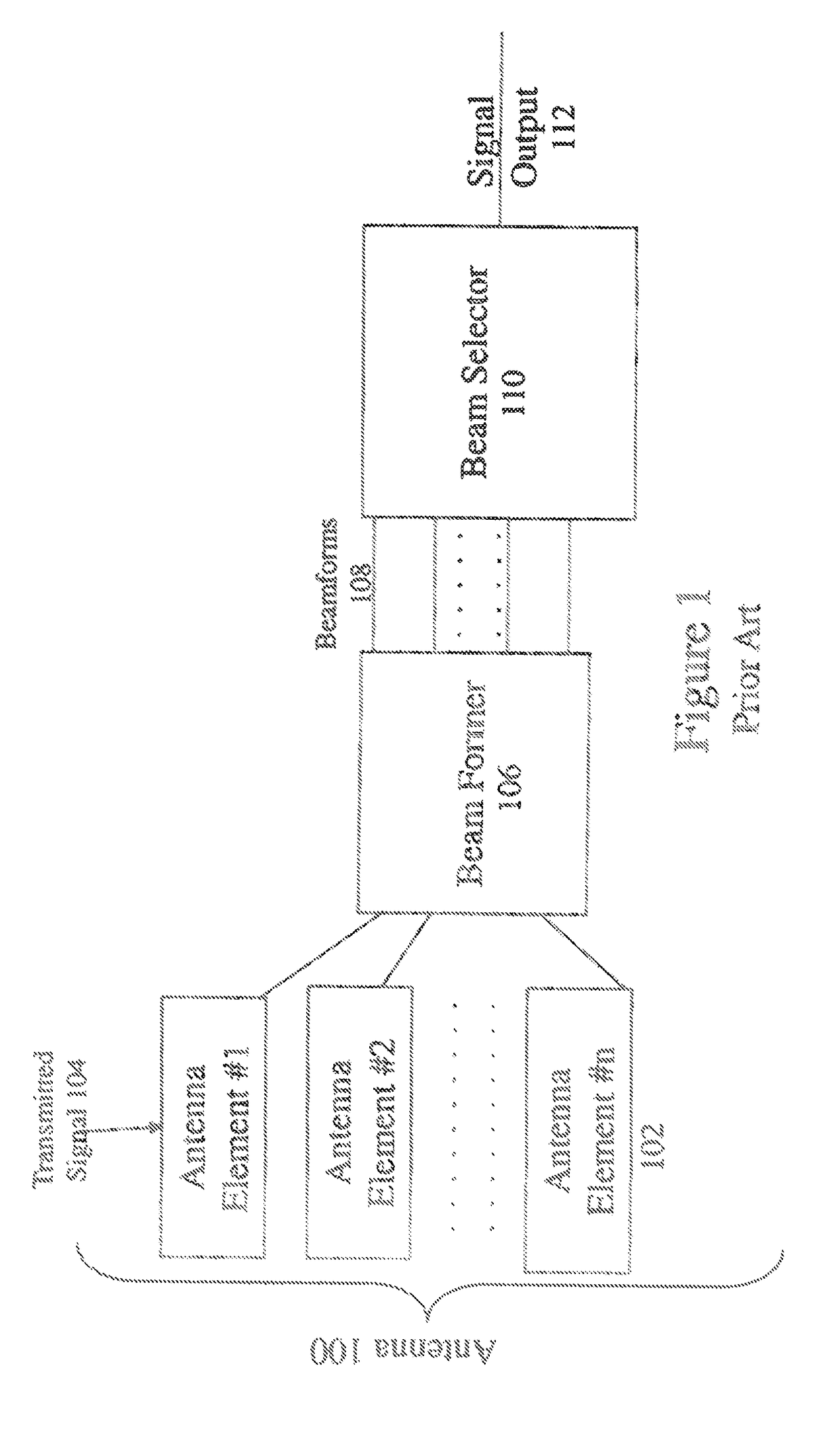
FIELD OF THE INVENTION[0001]The present invention relates generally to transmission of geolocation information, and, in particular, to the use of geolocation information to aid in antenna alignment.BACKGROUND OF THE INVENTION[0002]As an antenna moves, an output signal provided thereby gets better or worse and yields instant feedback so aiming the antenna in a proper direction is imperative. Analog signals gradually fade when signal strength decreases, when electromagnetic interference increases, or when multipath propagation increases. However, digital signal data is either perfect or non-existent at the receiving end, which implies the possibility of a sudden loss of digital signal reception known as the “cliff effect.” Antennas can be difficult to aim when outputting digital signals because of the cliff effect and because of delays in decoding and displaying the signal. Existing methods to resolve antenna positioning are provided by smart antennas which allow for an easier antenna...

Claims


Application Information

Patent Timeline
IPC IPC(8): H04B1/10H04L25/03H04H60/51H04B17/23H04H60/42H01Q1/12H04B17/14
CPCH04B1/1081H01Q1/125H04L25/0328H04H60/51H04B17/23H04H60/42H04B17/14A61H9/0078A61H2205/04A61H2201/1238A61H2201/1253A61H2201/165A61H2201/5071H04B7/00H04H60/14H04H60/41H04N5/50H04N21/438H04N21/4524H04N21/6143A61B2090/065A61B17/132A61B17/1327A61B17/135A61B2017/00827
Inventor SHAKER, REZASHAKER, ANISA
Owner UNIV OF SOUTHERN CALIFORNIA
Learn More