Method for Improving Aircraft Engine Operating Efficiency

a technology for aircraft engines and operating efficiency, applied in the direction of machines/engines, mechanical equipment, transportation and packaging, etc., can solve the problems of reducing the time available for warming up and cooling down aircraft engines, reducing engine operating efficiency, and minimizing this clearance, so as to increase the time aircraft spend on the ground, the effect of longer warm up and cooling down times

Inactive Publication Date: 2017-08-24
BOREALIS TECH LTD
View PDF0 Cites 14 Cited by
  • Summary
  • Abstract
  • Description
  • Claims
  • Application Information

AI Technical Summary

Benefits of technology

[0020]When the electric taxi systems-equipped aircraft are cleared for departure, the electric taxi systems are activated and controlled to drive the aircraft forward and / or reverse as required to push back from the parking location to an engine warm up location where the engines may be safely started without the risks posed by jet blast or engine ingestion. The aircraft is driven with the engines maintained in a low throttle condition, typically below idle thrust, and also with the electric taxi systems to an engine thrust location, typically on a takeoff runway, where the engines may require an idle thrust or a higher takeoff thrust. The electric taxi systems are inactivated at the engine thrust location, and the aircraft are then driven only with the engines to take off. The distance between the engine warm up location and the engine thrust location is selected to provide sufficient time for the engines to warm up and all for engine components to be heated evenly. When the aircraft driven by both the electric taxi systems and the engines at low thrust reaches the engine thrust location, an extended period of controlled warm up will have occurred before higher engine thrust is required, and the engine and engine components will be in an optimal thermal state without disturbing the controlled warm-up process.
[0021]The present method enables aircraft engines to be designed with longer warm up and cool down times than are presently required without delaying push back, taxi-in, and ground servicing, increasing the time aircraft spend on the ground, or otherwise adversely affecting airport operations.

Problems solved by technology

A primary cause of engine damage that interferes with engine operating efficiency is associated with a reduction in the time available for warming up and cooling down the aircraft's engines when an aircraft is on the ground prior to takeoff and after landing.
However, minimizing this clearance presents challenges.
As a result, there may be insufficient blade tip clearance, and the blade tip may contact or rub the shroud or static seal, or there may be excess clearance.
In the first instance, rotation of the turbine rotor may be adversely affected and the blade tip and / or shroud or static seal may be damaged, reducing the lives of these engine components.
In the second instance, poor engine performance may result.
Tip clearance loss may account for a significant amount of engine airflow loss, potentially in the range of about 20% to 40%, depending on the engine type.
When an optimum tight tip clearance gap is not maintained, the leakage airflow may induce unsteady heat loads onto the engine rotor casing, resulting in significant thermal stresses at the turbine blade tip.
As noted, the time pressures exerted by airlines and airport operators to keep aircraft moving into and out of gates and taking off after a relatively short engine warm up time may result in adverse effects on engine operation in flight.
The art has not provided a solution to this dilemma.

Method used


Image

  • Method for Improving Aircraft Engine Operating Efficiency
  • Method for Improving Aircraft Engine Operating Efficiency
  • Method for Improving Aircraft Engine Operating Efficiency

Examples


Embodiment Construction

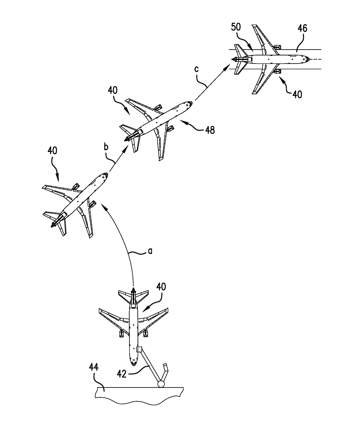
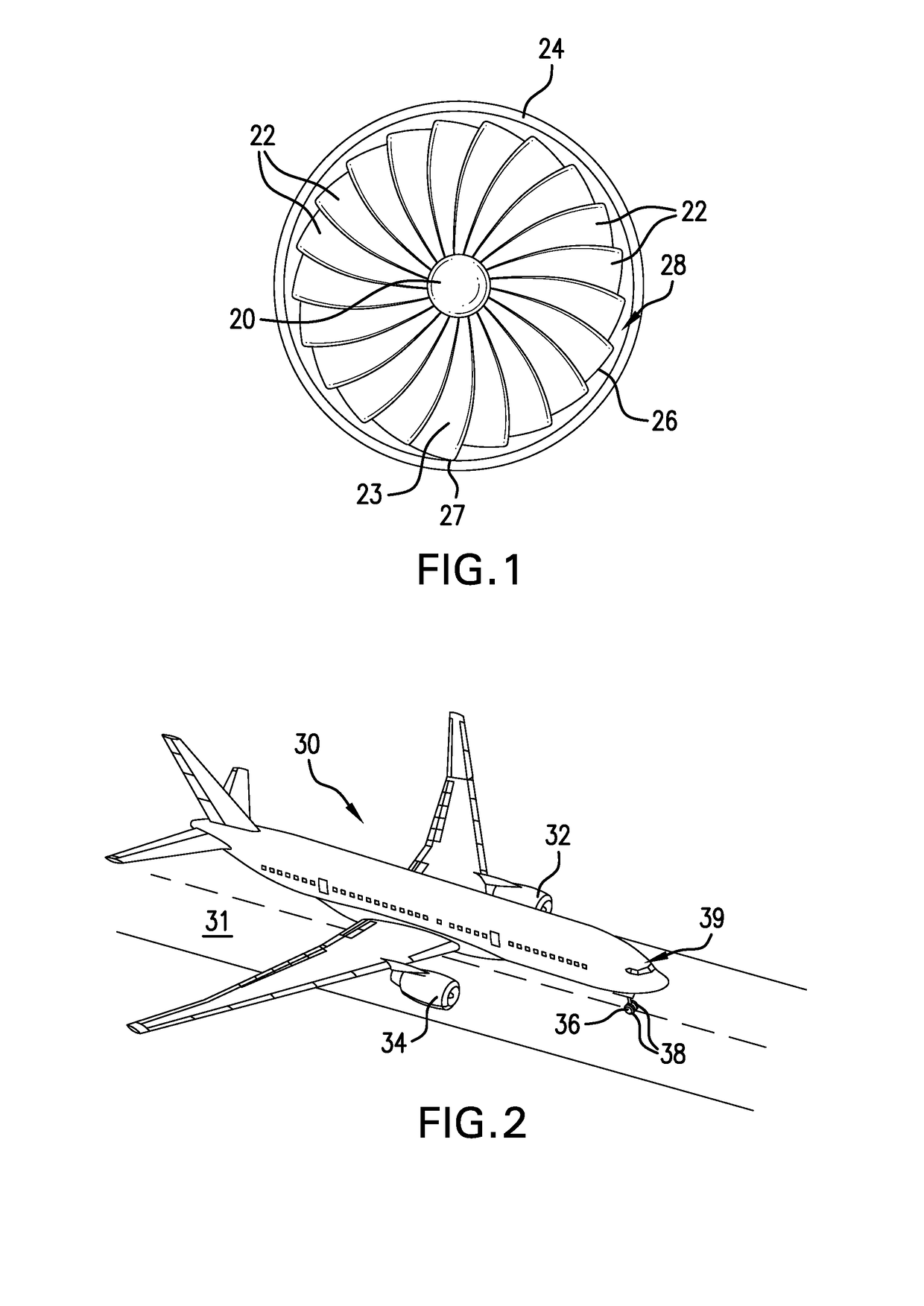
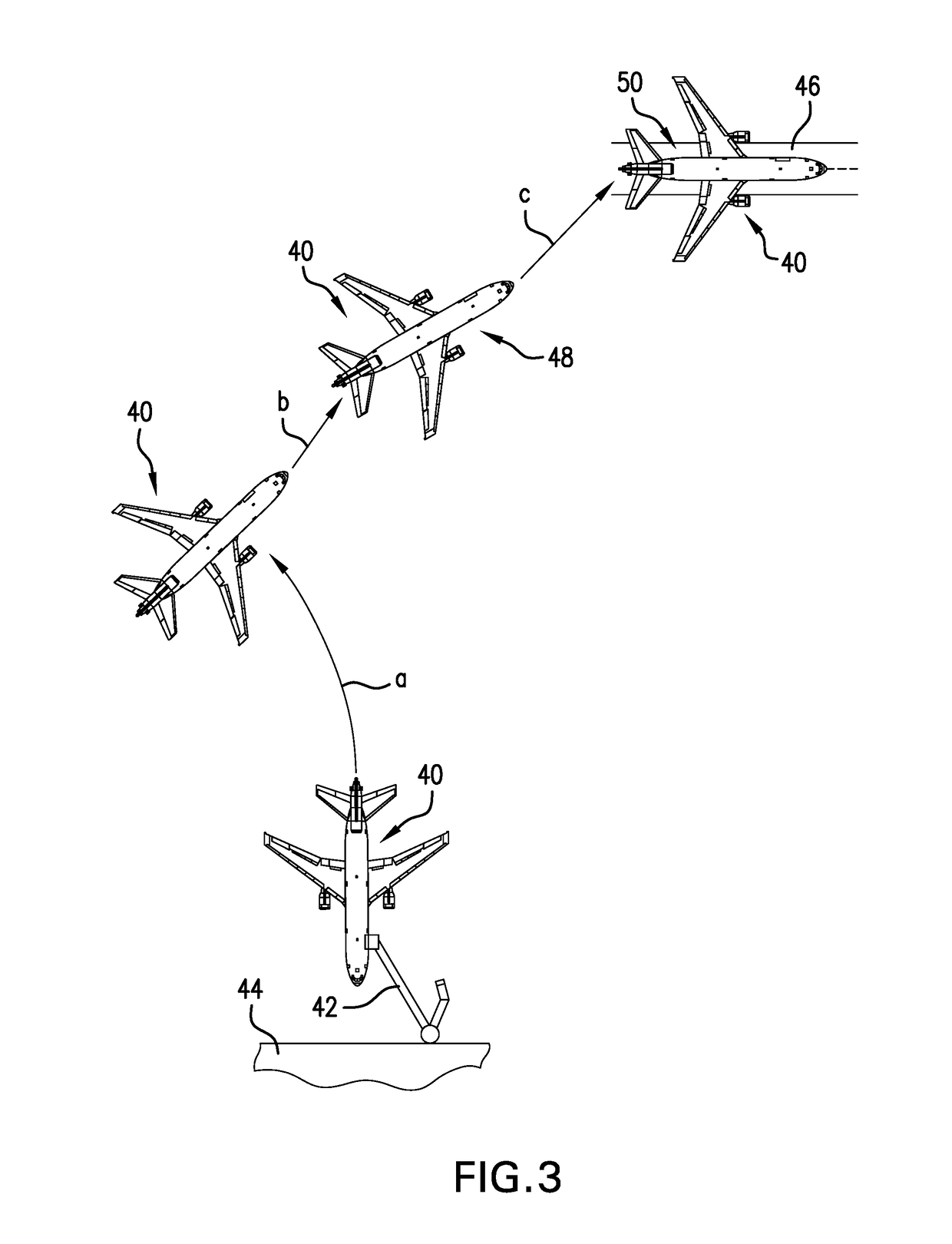
[0025]As discussed above, current airport ground operating procedures and the pressures resulting from minimizing aircraft time on the ground between landing and take off may not provide an optimum, or even a sufficient, amount of time to adequately warm up aircraft engines. An adequate engine warm up time prevents damage to engine components, for example rotor bowing where distorted rotors cannot maintain optimum rotor blade tip clearance during flight. Engine operating efficiency may be reduced when aircraft engine components are damaged or distorted as a result of an improperly warmed up or cooled down engine. Aircraft engine designers must presently design and configure aircraft engines to conform to engine start times imposed by airport operators. At most airports, the time between when an aircraft engine is started prior to take off and the subsequent application of idle thrust or take off thrust is currently about 150 seconds, although engine start times may be shorter. While...


PUM


Abstract

A method is provided for improving aircraft engine operating efficiency during flight in aircraft driven on the ground by electric taxi systems that extends engine warm up and cool down time during ground operations without increasing the time an aircraft spends on the ground. Aircraft are driven by electric taxi systems between landing and take off with the main engines simultaneously maintained at throttle setting for time periods that ensure even and symmetrical heating or cooling for all engine components. When the aircraft reaches a location where idle or take off thrust is required before take off, engine thrust may be increased without the adverse effects of differential thermal expansion of engine components during flight. Aircraft engines may be designed to rely on electric taxi operation and extended warm up and cool down times without delaying push back or taxi-in or otherwise negatively impacting airport operations.

Description

PRIORITY CLAIM[0001]This application claims priority from U.S. Provisional Patent Application No. 62 / 299,475, filed 24 Feb. 2016, the disclosure of which is hereby fully incorporated herein by reference.TECHNICAL FIELD[0002]The present invention relates generally to producing improvements in operating efficiency and performance of aircraft engines and specifically to a method for improving the operating efficiency and performance of aircraft engines in aircraft equipped with electric taxi systems for autonomous ground movement.BACKGROUND OF THE INVENTION[0003]Increasing aircraft engine operating efficiency and performance has many benefits. When aircraft engines operate with optimum efficiency during flight, not only is fuel saved, but engine life may also be extended. The frequency of required engine repairs and the cost of engine maintenance may also be reduced. A primary cause of engine damage that interferes with engine operating efficiency is associated with a reduction in the ...

Claims


Application Information

Patent Timeline
Patent Type & Authority Applications(United States)
IPC IPC(8): B64C19/02B64D31/00B64D41/00B64C25/40
CPCB64C19/02B64D41/00B64D31/00B64C25/405Y02T50/80B64C25/50F01D5/081F01D25/08
Inventor COX, ISAIAH W.
Owner BOREALIS TECH LTD
Why Eureka
Try Eureka