

Fault current limiter having self-checking power electronics and triggering circuit
a technology of fault current limiter and self-checking power electronics, which is applied in the direction of emergency protective arrangements for limiting excess voltage/current, instruments, pulse techniques, etc., can solve the problems of failure of solid state switches just evident, and insufficient energy used to blow fuse in control legs to protect networks from damage to first peak faults
- Summary
- Abstract
- Description
- Claims
- Application Information
AI Technical Summary
Benefits of technology
Problems solved by technology
Method used
Image


Examples
Embodiment Construction
[0013]The present embodiments will now be described more fully hereinafter with reference to the accompanying drawings, where some embodiments are shown. The subject matter of the present disclosure may be embodied in many different forms and are not to be construed as limited to the embodiments set forth herein. These embodiments are provided so this disclosure will be thorough and complete, and will fully convey the scope of the subject matter to those skilled in the art. In the drawings, like numbers refer to like elements throughout.
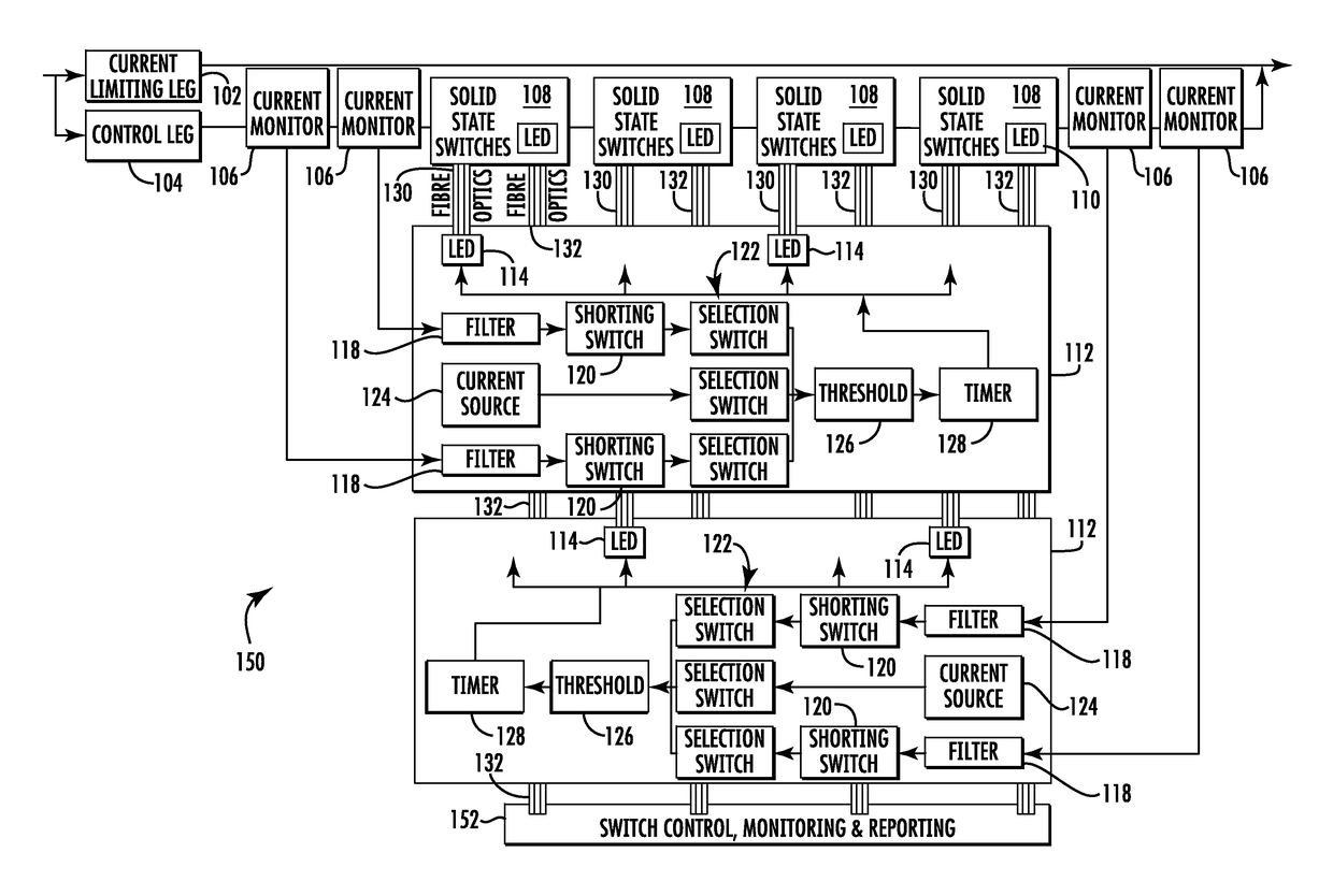
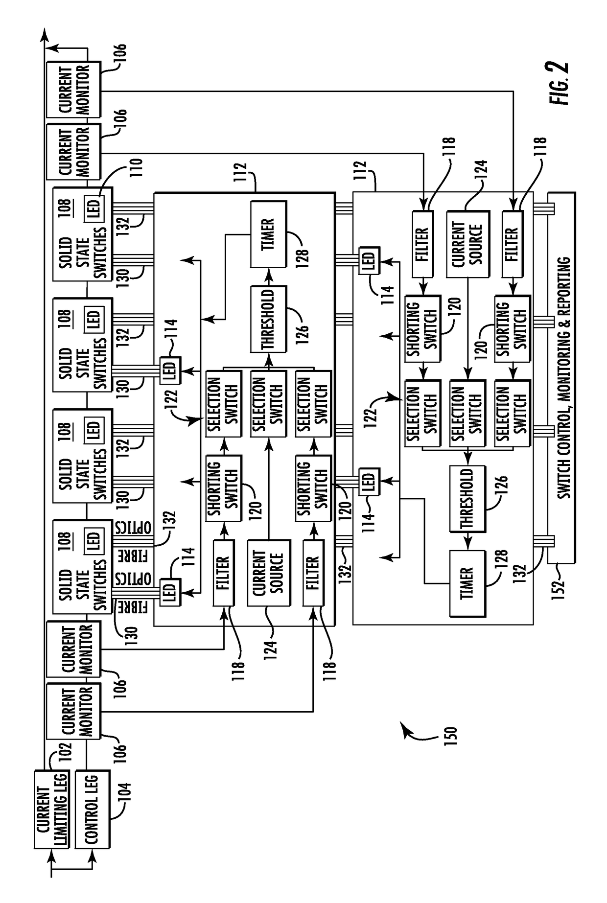
[0014]The present embodiments involve apparatus, systems and methods for improved fault current protection. Various embodiments address issues related to failure on demand for fault protection by providing circuitry architecture and techniques to facilitate checking components of a fault current limiter including detection circuits and power electronics. Various embodiments provide a control leg of a fault current limiter including a plurality of cur...
PUM
 Abstract
Description
Claims
Application Information