Gate pre-positioning for fast turn-off of synchronous rectifier

Active Publication Date: 2017-08-24
SEMICON COMPONENTS IND LLC
View PDF11 Cites 10 Cited by
  • Summary
  • Abstract
  • Description
  • Claims
  • Application Information

AI Technical Summary

Problems solved by technology

The conduction loss of a diode rectifier contributes significantly to the over

Method used


Image

  • Gate pre-positioning for fast turn-off of synchronous rectifier
  • Gate pre-positioning for fast turn-off of synchronous rectifier
  • Gate pre-positioning for fast turn-off of synchronous rectifier

Examples


Embodiment Construction

[0021]In the present disclosure, numerous specific details are provided, such as examples of circuits, components, and methods, to provide a thorough understanding of embodiments of the invention. Persons of ordinary skill in the art will recognize, however, that the invention can be practiced without one or more of the specific details. In other instances, well-known details are not shown or described to avoid obscuring aspects of the invention.

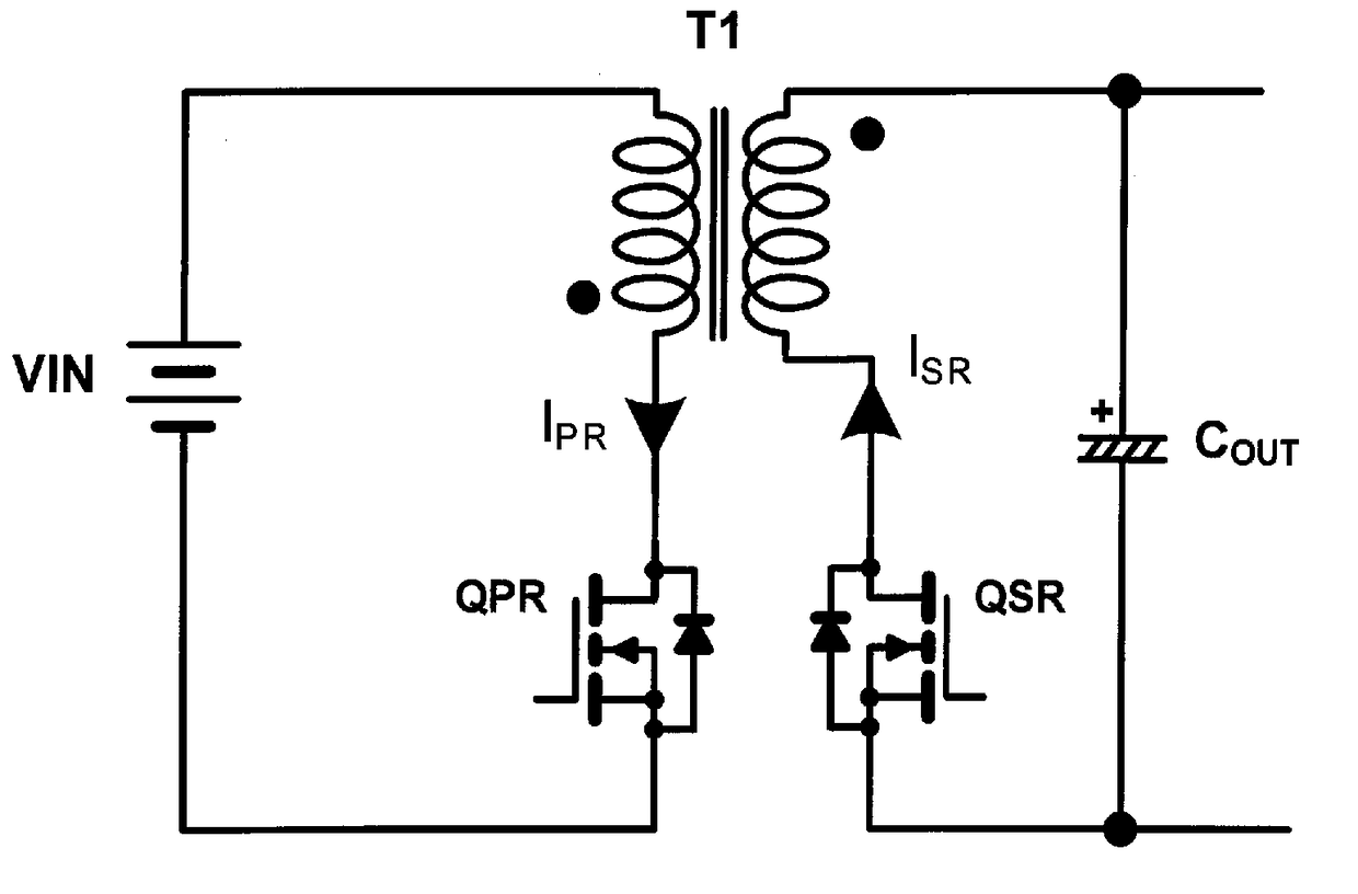
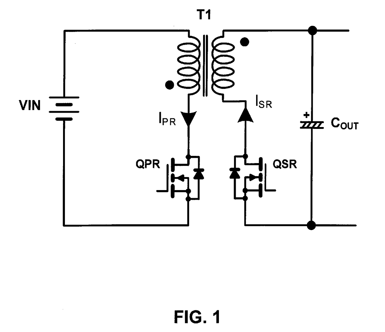
[0022]FIG. 1 shows a schematic diagram of a flyback converter that may take advantage of embodiments of the present invention. In the example of FIG. 1, the flyback converter includes a primary-side switch QPR, a synchronous rectifier QSR, a transformer T1, and an output capacitor COUT. In one embodiment, the primary-side switch QPR and the synchronous rectifier QSR are MOSFETs.

[0023]When the primary-side switch QPR is turned ON, the primary winding of the transformer T1 is connected to the input voltage source VIN, resulting in a primary-si...


PUM


Abstract

A synchronous rectifier driver pre-positions a gate of a synchronous rectifier to allow for fast turn-off. The synchronous rectifier driver turns ON the synchronous rectifier by driving the gate at a high level for a period of time that is based on a previous conduction time of the synchronous rectifier. The synchronous rectifier driver thereafter drives the gate at a lower level that is sufficient to keep the synchronous rectifier ON. The synchronous rectifier can be quickly turned OFF by further reducing the level of the drive signal at the gate of the synchronous rectifier.

Description

CROSS-REFERENCE TO RELATED APPLICATION[0001]The present application claims the benefit of U.S. Provisional Application No. 62 / 298,306, filed on Feb. 22, 2016, which is incorporated herein by reference in its entirety.BACKGROUND OF THE INVENTION[0002]1. Field of the Invention[0003]The present invention relates generally to electrical circuits, and more particularly but not exclusively to synchronous rectifiers.[0004]2. Description of the Background Art[0005]Rectifier diodes are employed in switching converters, such as flyback converters. Generally speaking, a flyback converter is a buck-boost converter where the output inductor is split to form a transformer. In a flyback converter, a primary-side switch is closed to connect the primary winding of the transformer to an input voltage source. Closing the primary-side switch increases the primary current and magnetic flux, stores energy in the transformer, and induces current on the secondary winding of the transformer. The induced cur...

Claims


Application Information

Patent Timeline
IPC IPC(8): H02M3/335
CPCH02M3/33592H02M1/36Y02B70/10H02M1/08H02M1/0054
Inventor CHOI, HANGSEOKHUANG, WEI-HSUANCHEN, CHENG-SUNG
Owner SEMICON COMPONENTS IND LLC
Why Eureka
Try Eureka