Active grille shutter and shutter subassembly for use with active grill shutters

a technology for active grille shutters and shutter sub-assemblies, which is applied in the direction of mechanical equipment, machines/engines, transportation and packaging, etc., can solve the problems of difficult assembly, frequent use of link mechanisms and actuators, and increased clearance between certain components, so as to reduce manufacturing and assembly costs, improve assembly ease, and maintain reliable and noise-free performance

Inactive Publication Date: 2017-08-31
MONTAPLAST OF NORTH AMERICA
View PDF7 Cites 30 Cited by
  • Summary
  • Abstract
  • Description
  • Claims
  • Application Information

AI Technical Summary

Benefits of technology

[0012]In this way, the active grille shutter and shutter subassembly overcome the disadvantages in the prior art by facilitating significantly improved ease of assembly. Moreover, the grille shutter assembly and shutter subassembly afford opportunities for decreased manufacturing and assembly costs while maintaining durable, reliable, and noise-free performance under a number of different vehicle operating conditions.

Problems solved by technology

One disadvantage with conventional grille shutters is that they frequently employ link mechanisms and actuators which are complex to manufacture and which are typically exposed to debris and environmental contaminants.
In addition, conventional grille shutters often necessitate that the fins flex or bend significantly in order to allow them to be installed to the frame, which complicates assembly and may require increased clearances to be provided between certain components.
Here, increased tolerances can result in rattles or other noise generation during use under certain operating conditions.
Moreover, in certain vehicle applications, the fins can be relatively large and may require correspondingly large tooling for manufacturing.

Method used


Image

  • Active grille shutter and shutter subassembly for use with active grill shutters
  • Active grille shutter and shutter subassembly for use with active grill shutters
  • Active grille shutter and shutter subassembly for use with active grill shutters

Examples


Embodiment Construction

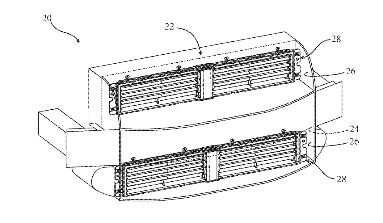
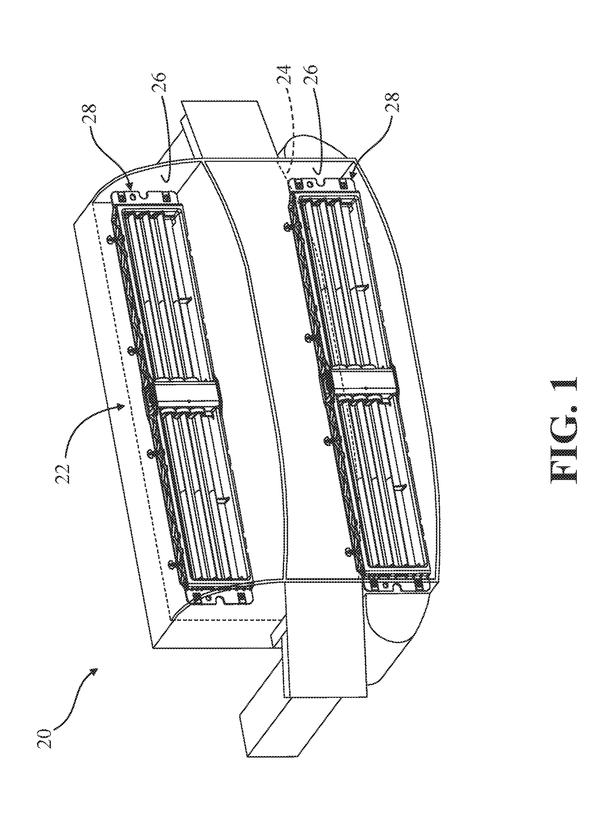
[0029]Referring now to the drawings, where like numerals are used to designate like structure, a portion of a vehicle is illustrated at 20 in FIG. 1. The vehicle 20 includes a heat exchanger, depicted generally at 22, which is mounted to a chassis support member 24 adjacent to an engine compartment of the vehicle 20, such as a frame member, a brace, a “core support,” and the like. The chassis support member 24 has upper and lower grille openings 26 to allow ambient air to be taken in and cool the heat exchanger 22. Adjacent to each grille opening 26, the vehicle 20 includes an active grille shutter, generally indicated at 28, according to one embodiment of the present invention. The active grille shutter assemblies 28 are employed for use in regulating airflow towards one or more heat exchangers 22 of the vehicle 20, as described in greater detail below. As illustrated, the vehicle 20 is a passenger automobile, but could be any type of vehicle, such as a heavy-duty truck, train, air...


PUM


Abstract

An active grille shutter for regulating airflow towards a vehicle heat exchanger. A frame adjacent the heat exchanger has a first mount with bores, a second mount, and an opening between the mounts to allow air to pass through. An end cap secures to the second mount and has bores. Vanes extend across the opening between opposing ends with a receiver at each end. Bearings are provided with couplers extending into and attached to the receivers, and a shafts extending into the bores. A linkage interconnects the bearings at one of the ends such that the vanes rotate concurrently. An actuator attached to the frame adjacent the first mount is coupled to one of the end cap bearings and rotation imparts rotation to the vanes by the linkage to concurrently rotate the vanes within the opening to regulate airflow through the opening towards the heat exchanger.

Description

CROSS-REFERENCE TO RELATED APPLICATION[0001]The subject patent application claims priority to and all the benefits of U.S. Provisional Patent Application Ser. No. 62 / 301,310 which was filed on Feb. 29, 2016, the disclosure of which is hereby incorporated by reference.BACKGROUND OF THE INVENTION[0002]1. Field of the Invention[0003]The present invention relates, generally, to shutter assemblies for vehicles and, more specifically, to an active grille shutter for a vehicle and to a shutter subassembly for use with an active grille shutter for a vehicle.[0004]2. Description of the Related Art[0005]Grille shutters are used in connection with regulating airflow towards one or more heat exchangers used in connection with a powertrain of a vehicle, such as an automotive passenger vehicle. Heat exchangers are commonly used to regulate the temperature of various fluids circulated in internal combustion engines, whereby heat is typically removed from the fluid as it flows through the heat exch...

Claims


Application Information

Patent Timeline
Patent Type & Authority Applications(United States)
IPC IPC(8): F01P7/10B60K11/08
CPCB60K11/085F01P7/10B60K11/08Y02T10/88
Inventor WOLF, ROBERTKERN, WOLFGANGKLAUSEN, SASCHA
Owner MONTAPLAST OF NORTH AMERICA
Why Eureka
Try Eureka