Control device for internal combustion engine

a control device and internal combustion engine technology, applied in electric control, vehicle heating/cooling devices, vehicle components, etc., can solve the problems of difficult to restore the rotation the internal combustion engine is to be stopped, and the crankshaft speed of the internal combustion engine is rapidly dropped, so as to prevent the torque of the auxiliary machin

Active Publication Date: 2017-08-31
TOYOTA JIDOSHA KK
View PDF1 Cites 7 Cited by
  • Summary
  • Abstract
  • Description
  • Claims
  • Application Information

AI Technical Summary

Benefits of technology

[0006]The invention provides a control device for an internal combustion engine that is capable of inhibiting an engine stall situation even in a case where the maximum value of the shaft torque that can be realized in the internal combustion engine has no room.
[0011]In the device described above, the maximum torque is variably set in accordance with the temperature of the outside air and the pressure of the outside air, and thus the torque difference described above can be more accurately calculated than in the case of no variable setting. Accordingly, a situation can be inhibited in which the processing for decreasing the auxiliary machine load torque applied to the crankshaft by the predetermined auxiliary machine is carried out by the predetermined speed being raised in a case where the maximum value of the shaft torque capable of being realized has room.
[0015]In the aspect described above, the electronic control unit may be configured to set the predetermined speed to a value increasing in two or more steps or continuously as the torque difference decreases. The amount of a decline in the rotation speed of the internal combustion engine allowing the restoration to the target speed without decreasing the auxiliary machine load torque applied to the crankshaft by the auxiliary machine decreases as the room in the maximum value of the shaft torque capable of being realized in the internal combustion engine decreases. In this regard, the predetermined speed can be variably set to at least three values in the device described above, and thus the predetermined speed can be set to the minimum level possible depending on the margin of the maximum value of the shaft torque. Accordingly, it is possible to prevent the auxiliary machine load torque applied to the crankshaft by the predetermined auxiliary machine from being minimized.

Problems solved by technology

When the auxiliary machine load torque exceeds the maximum value of the shaft torque that can be realized in the internal combustion engine, the rotation speed of the crankshaft of the internal combustion engine rapidly drops, which may cause the internal combustion engine to be stopped (engine stall).
During the idle operation of the internal combustion engine, the reduction processing unit decreases the auxiliary machine load torque applied to the crankshaft by the predetermined auxiliary machine prior to a situation in which the rotation speed of the internal combustion engine is reduced for any reason and it becomes difficult to restore the rotation speed of the internal combustion engine to the target speed so that the occurrence of the engine stall can be inhibited eventually.
It is more difficult to restore the rotation speed of the internal combustion engine to the target speed in a case where the maximum value of the shaft torque has no room against the auxiliary machine load torque applied to the crankshaft by the auxiliary machine than in a case where the maximum value of the shaft torque has room against the auxiliary machine load torque applied to the crankshaft by the auxiliary machine in a case where the rotation speed of the internal combustion engine is reduced for any reason.
Accordingly, in a case where the predetermined speed is set on the assumption that the maximum value of the shaft torque has room, the processing performed by the reduction processing unit so as to decrease the auxiliary machine load torque applied to the crankshaft by the auxiliary machine will not suffice in a case where the maximum value of the shaft torque has no room and the engine stall could occur.
In a case where the predetermined speed is set on the assumption that the maximum value of the shaft torque has no room, in contrast, the processing performed by the reduction processing unit so as to decrease the auxiliary machine load torque could be unnecessarily executed in a case where the maximum value of the shaft torque has room.

Method used


Image

  • Control device for internal combustion engine
  • Control device for internal combustion engine
  • Control device for internal combustion engine

Examples


first embodiment

[0022]Hereinafter, a first embodiment of a rotation speed control device for an internal combustion engine will be described in detail with reference to accompanying drawings.

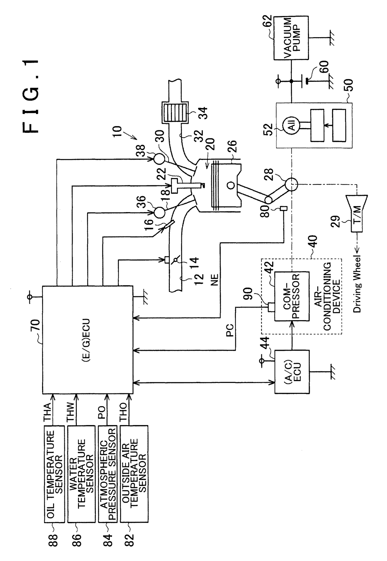
[0023]An internal combustion engine 10 that is illustrated in FIG. 1 is a low-displacement (for example, “1,500 cc” or less) engine. A throttle valve 14 is disposed in an intake passage 12 of the internal combustion engine 10. The throttle valve 14 adjusts the flow path area of the intake passage 12. In the intake passage 12, a fuel injection valve 16 is disposed downstream from the throttle valve 14. An air-fuel mixture of the air that is suctioned into the intake passage 12 and the fuel that is injected by the fuel injection valve 16 is suctioned into a combustion chamber 20 as a result of the opening of an intake valve 18. A spark plug 22 is disposed in the combustion chamber 20. The air-fuel mixture that is suctioned into the combustion chamber 20 is combusted when the spark plug 22 performs an ignition ope...

second embodiment

[0058]Hereinafter, a second embodiment of the rotation speed control device for an internal combustion engine will be described with reference to accompanying drawings. The following description will focus on how the second embodiment differs from the first embodiment.

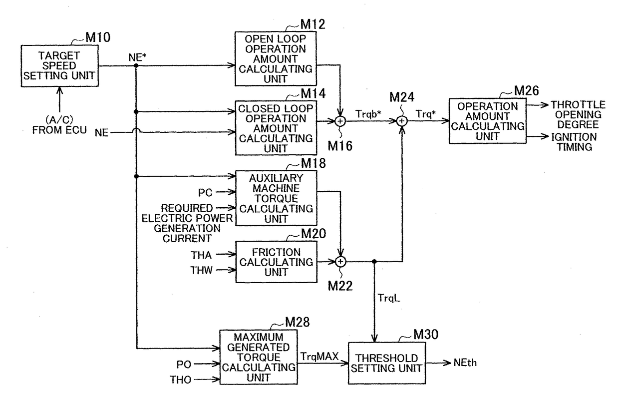
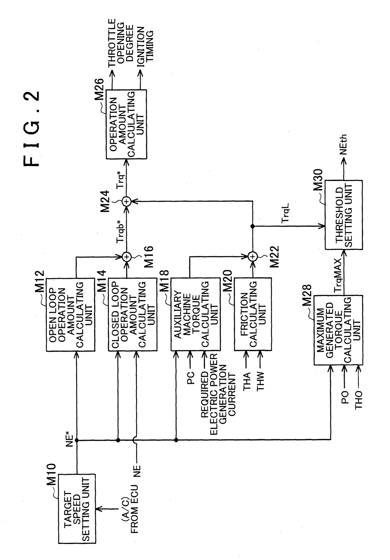
[0059]In the first embodiment described above, the predetermined speed NEth is set to one of the reference value B and the anti-stall value A. In this embodiment, however, the predetermined speed NEth is continuously changed in accordance with the value that is obtained by subtracting the load torque TrqL from the maximum torque TrqMAX. Specifically, a continuously increasing value is set as the predetermined speed NEth as the value that is obtained by subtracting the load torque TrqL from the maximum torque TrqMAX decreases.

[0060]FIG. 5A illustrates how the maximum torque TrqMAX and the load torque TrqL change, and FIG. 5B illustrates how the rotation speed NE and the predetermined speed NEth change. In this embodimen...


PUM


Abstract

An ECU avoids engine stall by putting a compressor into a stationary state in a case where the rotation speed of a crankshaft is equal to or less than a predetermined speed during an idle operation of an internal combustion engine. During the idle operation, the ECU calculates a total load torque applied to the crankshaft by the compressor and an alternator. The ECU calculates the maximum torque of the internal combustion engine during the idle operation based on a target speed during the idle operation. Then, the ECU raises the predetermined speed in a case where the value obtained by subtracting the load torque from the maximum torque is equal to or less than a predetermined value.

Description

BACKGROUND OF THE INVENTION[0001]1. Field of the Invention[0002]The invention relates to a control device for an internal combustion engine that is applied to a vehicle traveling by using the power of the internal combustion engine and provided with an auxiliary machine which is driven by the power of the internal combustion engine.[0003]2. Description of Related Art[0004]Rotation speed control for reaching a target speed by using the calculation of a required torque for an internal combustion engine during an idle operation based on a load torque applied to the internal combustion engine and the operation of an actuator of the internal combustion engine in accordance with the required torque is disclosed in, for example, Japanese Patent Application Publication No. 10-325349. Herein, the load torque includes an auxiliary machine load torque applied to a crankshaft by an auxiliary machine.SUMMARY OF THE INVENTION[0005]For the rotation speed to be controlled to reach the target speed ...

Claims


Application Information

Patent Timeline
Patent Type & Authority Applications(United States)
IPC IPC(8): F02D41/08
CPCF02D41/083F02D2200/703F02D2200/1002B60H1/3208B60H2001/3273F02D31/003F02D41/16F02D2250/24
Inventor FUKUDA, ATSUSHISHINAGAWA, TOMOHIRO
Owner TOYOTA JIDOSHA KK
Why Eureka
Try Eureka