Mating electrodes for resistance spot welding of aluminum workpieces to steel workpieces

a technology of resistance spot welding and welding electrodes, which is applied in the direction of electrode features, welding/soldering/cutting articles, manufacturing tools, etc., can solve the problems of surface oxide residues, surface oxide residues, and weld defects most commonly found in such a disruptive dispersion, and achieve the effect of reducing the strength of the join

Active Publication Date: 2017-09-07
GM GLOBAL TECH OPERATIONS LLC
View PDF8 Cites 18 Cited by
  • Summary
  • Abstract
  • Description
  • Claims
  • Application Information

AI Technical Summary

Benefits of technology

[0002]The joining of a steel workpiece to a lighter-weight aluminum workpiece (unalloyed aluminum or an aluminum alloy having 85% by weight or more aluminum) provides a weight reduction, while retaining suitable strength, in many articles of manufacture. The practice offers many weight-saving opportunities such as, for example, in the manufacture of body panels and other body structural members for automotive vehicles. Many such parts have inner and outer panels that are complementarily shaped to provide a stronger more rigid structure as well as to enclose windows, closure members, insulation, electrical wiring, and the like. Such inner and outer panels have thicknesses, for example, from approximately 0.3 mm to 6 mm. The steel and aluminum workpieces are usually shaped with like-shaped peripheral edges or flanges that enable them to be joined with a series of suitably spaced resistance spot welds that are strategically located along their peripheries. A curable adhesive may also be applied between the facing surfaces to be joined in the closing of the panel structure to provide further bonding strength.
[0004]While joining an aluminum workpiece with a complementary steel workpiece can reduce the weight of a part being manufactured, the formation of one or more electrical resistance spot welds at the steel-to-aluminum faying interface is a challenging endeavor due to several factors that can be traced to the dissimilar nature of the workpieces. These factors include the presence of a surface oxide layer on the aluminum workpiece, the marked difference in the melting points of the steel and aluminum workpieces (about 1300° C.-1500° C. for steel and about 600° C. for aluminum), the significantly greater thermal and electrical conductivities of the aluminum workpiece compared to the steel workpiece, and the propensity for aluminum and steel to react with each other under intimate contact at elevated temperatures to form a brittle intermetallic layer at the bonding interface of the weld joint and the steel workpiece. The differing characteristics of the steel and aluminum workpieces, more specifically, can lead to the development and dispersal of weld defects at and along the bonding interface of the weld joint and the steel workpiece, which has an adverse effect on the strength of the joint including the strength in peel and cross-tension. The weld defects that are most commonly found in such a disruptive dispersal include surface oxide residues, porosity, microcracks, shrinkage voids, and residues from the thermal decomposition of any leftover adhesive films that remain at the weld location.SUMMARY

Problems solved by technology

While joining an aluminum workpiece with a complementary steel workpiece can reduce the weight of a part being manufactured, the formation of one or more electrical resistance spot welds at the steel-to-aluminum faying interface is a challenging endeavor due to several factors that can be traced to the dissimilar nature of the workpieces.
The differing characteristics of the steel and aluminum workpieces, more specifically, can lead to the development and dispersal of weld defects at and along the bonding interface of the weld joint and the steel workpiece, which has an adverse effect on the strength of the joint including the strength in peel and cross-tension.
The weld defects that are most commonly found in such a disruptive dispersal include surface oxide residues, porosity, microcracks, shrinkage voids, and residues from the thermal decomposition of any leftover adhesive films that remain at the weld location.

Method used


Image

  • Mating electrodes for resistance spot welding of aluminum workpieces to steel workpieces
  • Mating electrodes for resistance spot welding of aluminum workpieces to steel workpieces
  • Mating electrodes for resistance spot welding of aluminum workpieces to steel workpieces

Examples


Embodiment Construction

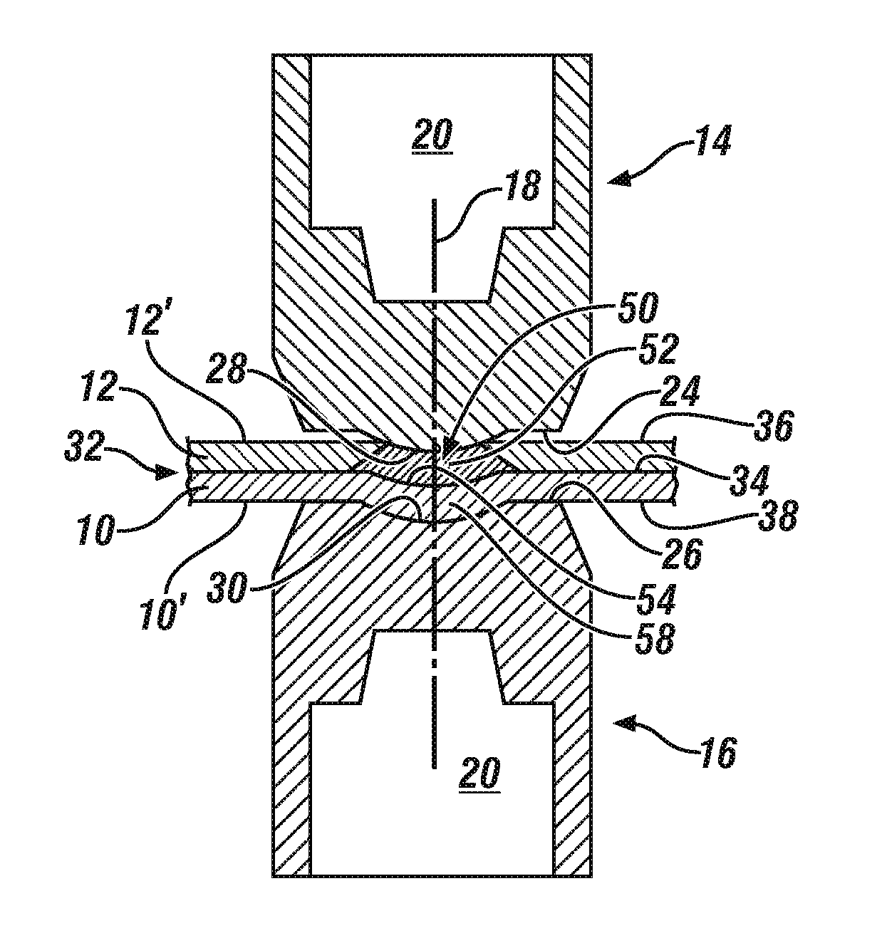
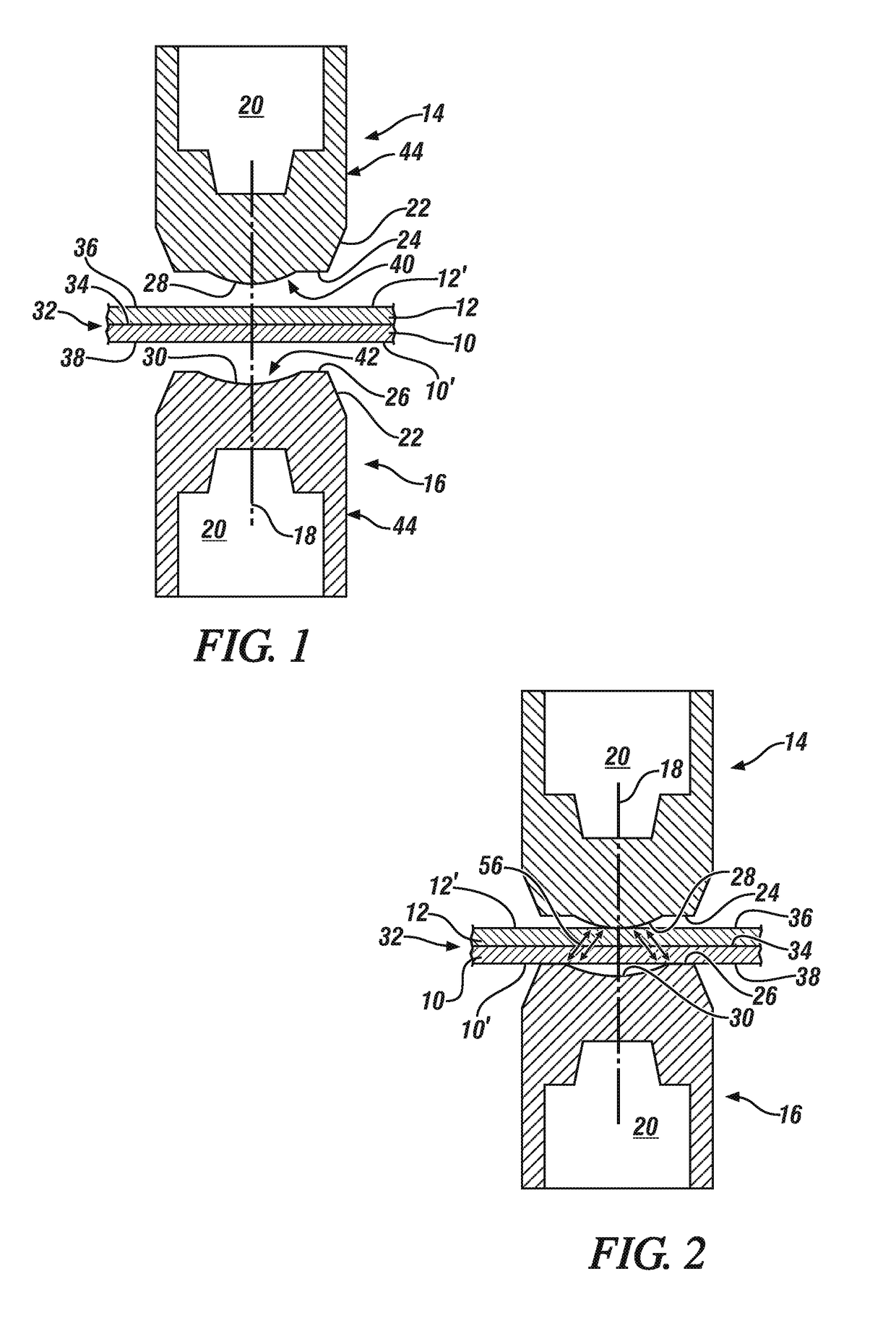
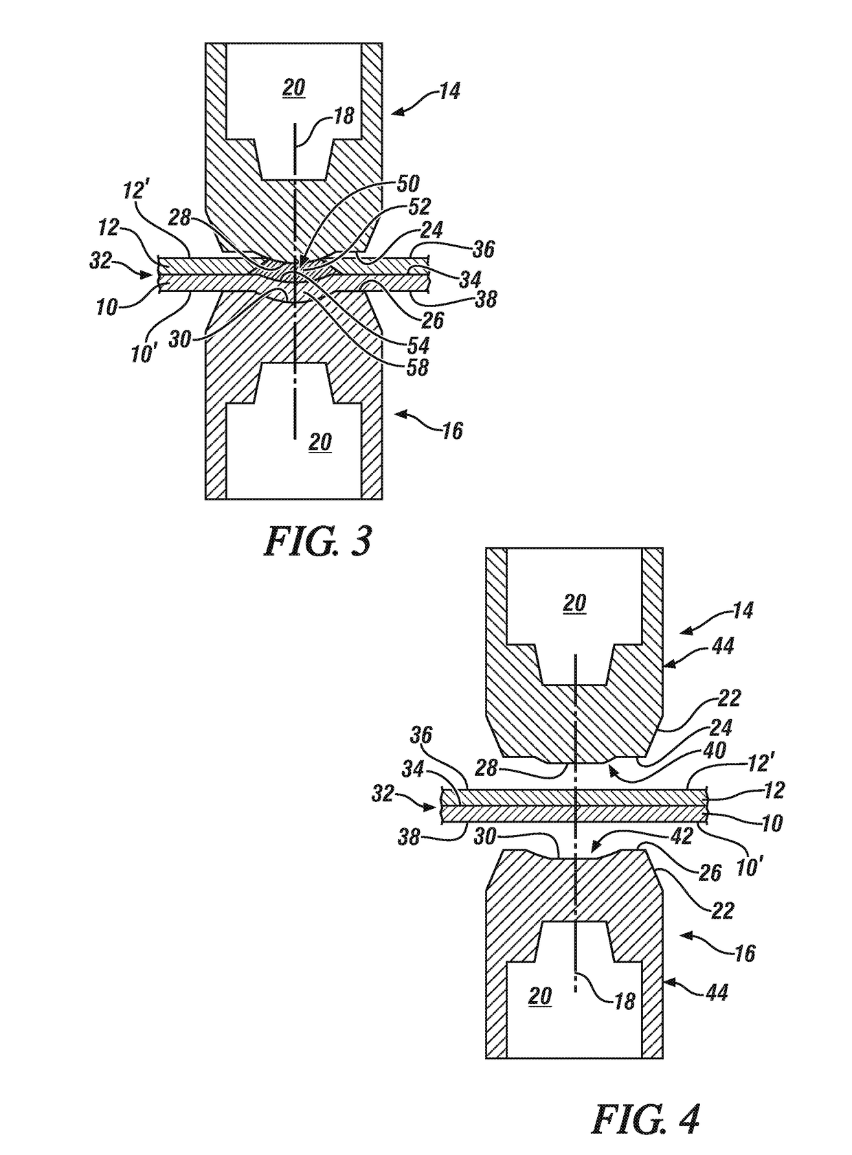
[0017]The present disclosure pertains to the design of opposing spot welding electrodes for use in forming resistance spot welds between an aluminum workpiece and a steel workpiece that are located adjacent to one another in a workpiece stack-up assembly. The spot welding electrodes used to form spot welds between an aluminum workpiece and a steel workpiece include mating weld faces. Specifically, one electrode has a weld face with a convex central portion for engagement with an outer surface of the stack-up assembly proximate the aluminum workpiece and the other, opposing electrode has a weld face with a complementarily shaped and sized concave central portion for engagement with the opposing outer surface of the stack-up assembly proximate the steel workpiece. The combination of the spot welding electrodes with their mating weld faces distributes the electrical current passing between the facing weld faces along a radially outwardly expanding flow path that extends from the electr...


PUM

PropertyMeasurementUnit
thicknessesaaaaaaaaaa
melting pointsaaaaaaaaaa

Abstract

A spot weld may be formed between an aluminum workpiece and an adjacent overlapping steel workpiece with the use of opposed spot welding electrodes that have mating weld faces designed for engagement with the outer surfaces of the workpiece stack-up assembly. The electrode that engages the stack-up assembly proximate the aluminum workpiece includes a central ascending convex surface and the electrode that engages the stack-up assembly proximate the steel workpiece has an annular surface. The mating weld faces of the first and second spot welding electrodes distribute the passing electrical current along a radially outwardly expanding flow path to provide a more uniform temperature distribution over the intended spot weld interface and may also produce a deformed bonding interface within the formed weld joint. Each of these events can beneficially affect the strength of the weld joint.

Description

CROSS-REFERENCE TO RELATED APPLICATION(S)[0001]This application claims priority to U.S. provisional application No. 62 / 301,690, which was filed on Mar. 1, 2016. The entire contents of the aforementioned provisional application are incorporated herein in their entirety.INTRODUCTION[0002]The joining of a steel workpiece to a lighter-weight aluminum workpiece (unalloyed aluminum or an aluminum alloy having 85% by weight or more aluminum) provides a weight reduction, while retaining suitable strength, in many articles of manufacture. The practice offers many weight-saving opportunities such as, for example, in the manufacture of body panels and other body structural members for automotive vehicles. Many such parts have inner and outer panels that are complementarily shaped to provide a stronger more rigid structure as well as to enclose windows, closure members, insulation, electrical wiring, and the like. Such inner and outer panels have thicknesses, for example, from approximately 0.3...

Claims


Application Information

Patent Timeline
Patent Type & Authority Applications(United States)
IPC IPC(8): B23K11/20B23K11/16B23K11/30B23K11/11
CPCB23K11/20B23K11/115B23K2203/166B23K11/3009B23K2203/20B23K11/163B23K11/11B23K11/30B23K2101/34B23K2103/20
Inventor WANG, HUI-PINGCARLSON, BLAIR E.SIGLER, DAVID R.KARAGOULIS, MICHAEL J.
Owner GM GLOBAL TECH OPERATIONS LLC
Why Eureka
Try Eureka