Steam Turbine Plant

a steam turbine and plant technology, applied in steam engine plants, leakage prevention, machines/engines, etc., can solve the problems of reducing the efficiency of the gas turbine (heat source device) and the rated load so as to reduce the differential effectively using the heat in the plant, and reducing the thermal expansion of the steam turbine.

Inactive Publication Date: 2017-09-07
MITSUBISHI HITACHIPOWER SYST LTD
View PDF7 Cites 5 Cited by
  • Summary
  • Abstract
  • Description
  • Claims
  • Application Information

AI Technical Summary

Benefits of technology

[0010]As described in JP-A-2010-138916, a method using the steam that flows in the steam passage of a steam turbine can use the heat only when the steam is generated from a steam generating device. Since the steam is normally and partially branched from a steam of the main stream by a protective shield, there is a possibility of lowering efficiency at rated load of the steam turbine.
[0012]The purpose of the invention is to provide a steam turbine plant that can reduce differential thermal expansion of a steam turbine by further effectively using heat in a plant, without affecting efficiency and control of a heat source device, and regardless of a presence or absence of steam generation by a steam generating device.
[0014]According to the invention, it is possible to reduce the differential thermal expansion of the steam turbine by further effectively using the heat in the plant, without affecting the efficiency and control of the heat source device, and regardless of the presence or absence of the steam generation by the steam generating device.

Problems solved by technology

As described in JP-A-2013-133825, since heat of fluid that does not finish a work in a gas turbine is used, in a method using steam generated by using exhaust heat from a gas turbine compressor, there is a possibility of lowering efficiency of the gas turbine (heat source device).
Since the steam is normally and partially branched from a steam of the main stream by a protective shield, there is a possibility of lowering efficiency at rated load of the steam turbine.

Method used


Image

  • Steam Turbine Plant
  • Steam Turbine Plant
  • Steam Turbine Plant

Examples


first embodiment

[0025]Control means for controlling the amount of heat input to a steam turbine and a steam turbine plant having this means according to the invention will be described with reference to drawings.

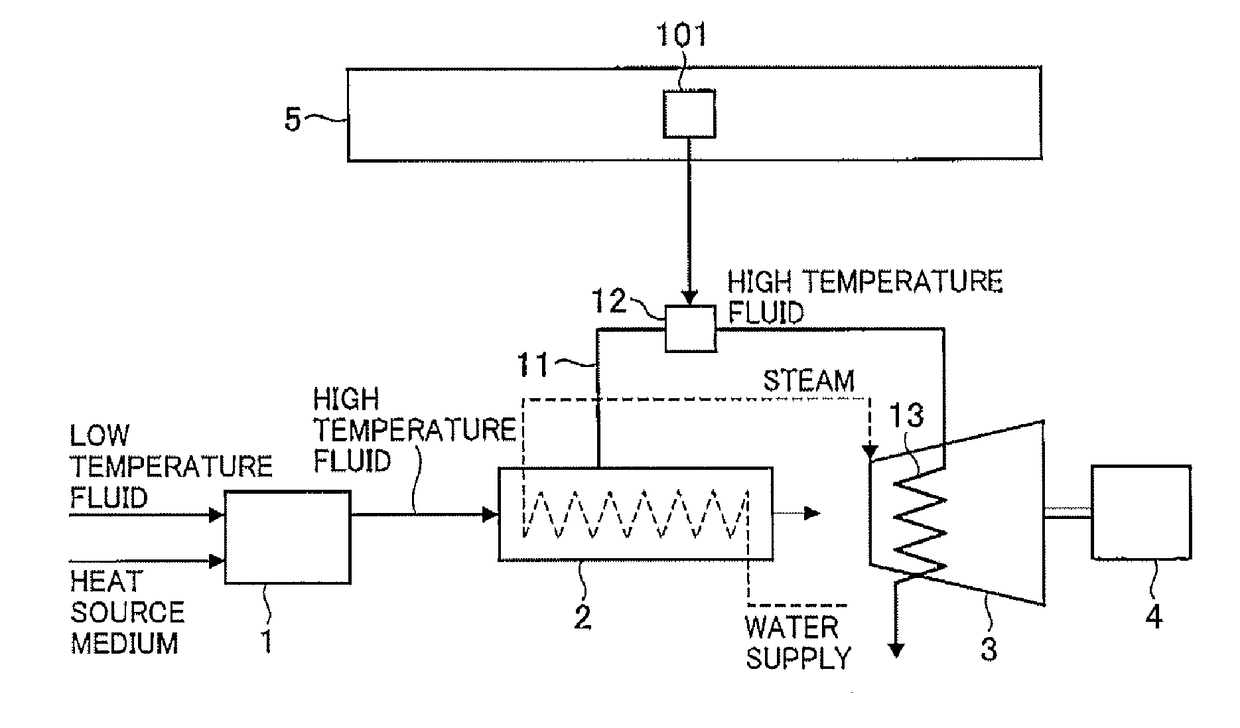
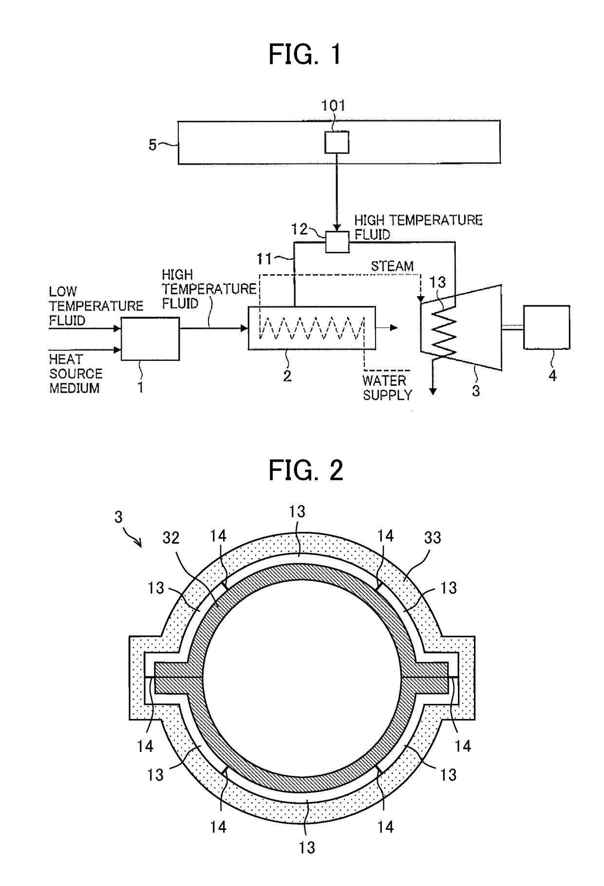
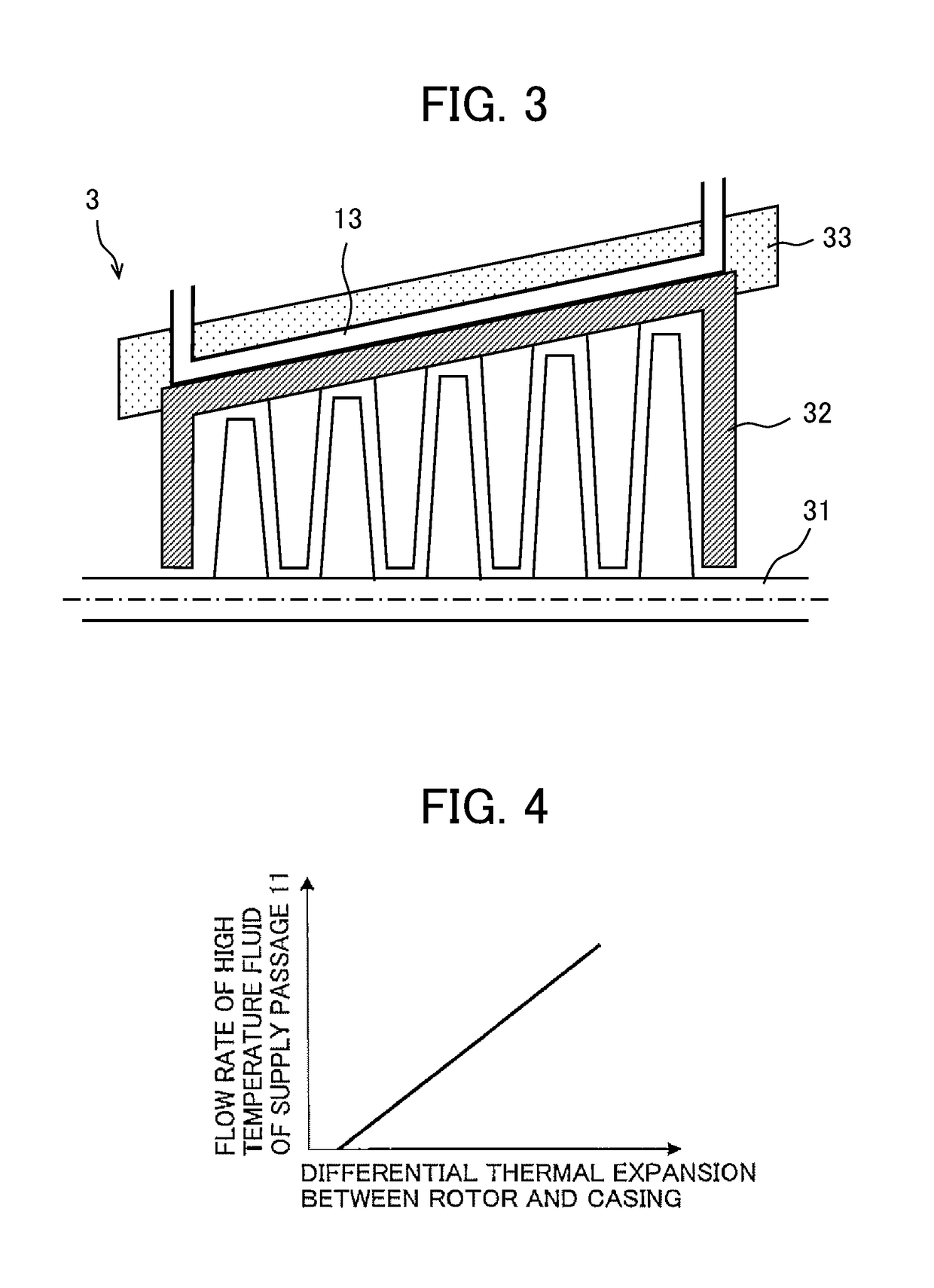
[0026]FIG. 1 is a schematic diagram illustrating a configuration of the steam turbine plant according to the embodiment. In FIG. 1, only configuration components and control circuits required for describing the invention are illustrated. FIG. 2 is a cross-sectional view in a turbine radial direction illustrating a schematic structure of a heating flow path of a casing of a steam turbine according to the embodiment, and FIG. 3 is a cross-sectional view in a turbine axial direction. In FIG. 2, drawings of a rotor, a moving blade, and a stationary blade are omitted, and in FIG. 3, only an upper half side of a turbine is illustrated.

[0027]The steam turbine plant of the embodiment is provided with a heat source device 1, a steam generating device 2, a steam turbine 3, a generator 4, and a plant ...

second embodiment

[0054]Although a case in which the cooling flow path 23 is disposed on the portion of the lower half of the casing 32 as the portion to be the relatively low temperature at the time of starting the plant is described as an example in the second embodiment, without being limited thereto, arrangement and number of the cooling flow path 23 may be determined by the analysis of the empirical knowledge or the known method of the heat transfer engineering. That is, the cooling flow path may be disposed on the upper half side of the casing 32 as the portion to be relatively low temperature, at the time of starting the plant. In addition, at the time of starting the plant, if the portion to be relatively low temperature and the portion to be the relatively high temperature is replaced, the cooling flow path and the heating flow path may be replaced. In such a case, it is possible to obtain the same effect as described above.

[0055]Although a case in which the heating flow path 13 is disposed ...


PUM


Abstract

A steam turbine plant of the present invention includes a heat source device that heats a low temperature fluid by a heat source medium to obtain a high temperature fluid, a steam generating device that generates steam by heat exchange with the high temperature fluid, a steam turbine that is driven by the steam, a heating flow path that is disposed on an outer surface of a casing of the steam turbine, a high temperature fluid supply passage that is branched from a flow path of the high temperature fluid in the steam generating device, is connected to the heating flow path, and supplies the high temperature fluid to the heating flow path, and a high temperature fluid flow rate regulating device that regulates a flow rate of the high temperature fluid flowing through the high temperature fluid supply passage.

Description

BACKGROUND OF THE INVENTION[0001]Field of the Invention[0002]The present invention relates to a steam turbine plant provided with a steam turbine such as a combined cycle power plant or a coal-fired power plant.[0003]Background Art[0004]Since the power generation amount varies greatly in a power generation plant using renewable energy represented by wind power generation or solar power generation, fast start-up (in other words, starting in a shorter period of time) of a power generation plant (steam turbine plant) provided with a steam turbine is required for the stabilization of the power system.[0005]In the fast start-up of the steam turbine, since a rotor of the steam turbine and a casing for housing the rotor are exposed to high temperature steam entering the steam turbine, the rotor and the casing are heated, and thermally expanded, and thus extend particularly in a turbine axial direction. Since a structure and heat capacity of the rotor are different from that of the casing, ...

Claims


Application Information

Patent Timeline
Patent Type & Authority Applications(United States)
IPC IPC(8): F01K21/04F01K13/02F01K11/02
CPCF01K21/045F01K13/02F01K11/02F01D25/10F01K7/16Y02E20/16F01D11/24F01D25/12
Inventor KIM, EUNKYEONGYOSHIDA, YASUHIROYOSHIDA, TAKUYAYASHIKI, TATSUROKAWATA, MIYUKIYAMANAKA, KAZUNORIIYANAGA, NORIHIROSUZUKI, FUMIYUKI
Owner MITSUBISHI HITACHIPOWER SYST LTD
Why Eureka
Try Eureka