Signal processing apparatus

a technology of signal processing and processing equipment, which is applied in the direction of fibre transmission, aircraft components testing, electromagnetic transmission, etc., can solve the problems of loss of signals carried by such coaxial cables, heavy coaxial cables, and low signal quality, and achieves space and weight saving, light amplifiers, and low power

Inactive Publication Date: 2017-09-07
BAE SYSTEMS PLC
View PDF4 Cites 4 Cited by
  • Summary
  • Abstract
  • Description
  • Claims
  • Application Information

AI Technical Summary

Benefits of technology

[0011]The present inventors have further realised that by locating the transmit high power amplifier and / or receive low noise amplifier close to an antenna, lower power, lighter amplifiers may be implemented. Thus, surprisingly, a space and weight saving may be achieved by separating the low level transmit signal generation and receive signal processing functions from the transmit high power amplifier and receive low noise amplifier.
[0012]Conventionally, space and weight reduction tend to result from integrating apparatus together so as to have fewer modules. However, the present inventors have realised that a space and weight reduction may be achieved by surprisingly doing the opposite of this, namely, separating the low level transmit signal generation and receive signal processing functions from the transmit high power amplifier and receive low noise amplifier.
[0013]The present inventors have further realised that the use of wideband optical fibre links tends to facilitate the separation of the low level transmit signal generation and receive signal processing functions from the transmit high power amplifier and receive low noise amplifier.
[0014]The present inventors have further realised that signal losses between the low level transmit signal generation and receive signal processing functions (which may be centrally located on an aircraft, e.g., in an equipment bay) and the transmit and receive amplifiers (which may be located proximate to an antenna, remote from the low level transmit signal generation and receive signal processing functions) may be reduced by using an optical communication link to relay signals between those units.
[0015]The present inventors have further realised that a lower power high power amplifier can be used given that the interconnection loss between the high power amplifier and antenna are significantly reduced as the two are in relatively close proximity.
[0016]The present inventors have further realised that a substantial weight saving may be achieved by connecting the low level transmit signal generation and receive signal processing functions to the transmit and receive amplifiers using an optical fibre communication link to relay signals, as opposed to an electrically conductive cable as is used conventionally.

Problems solved by technology

Such coaxial cable tends to be heavy.
Also, signals carried by such coaxial cable tend to experience loss (i.e. the coaxial cable tends to be “lossy”).
These amplifiers tend to be heavy.

Method used


Image

  • Signal processing apparatus
  • Signal processing apparatus
  • Signal processing apparatus

Examples


first embodiment

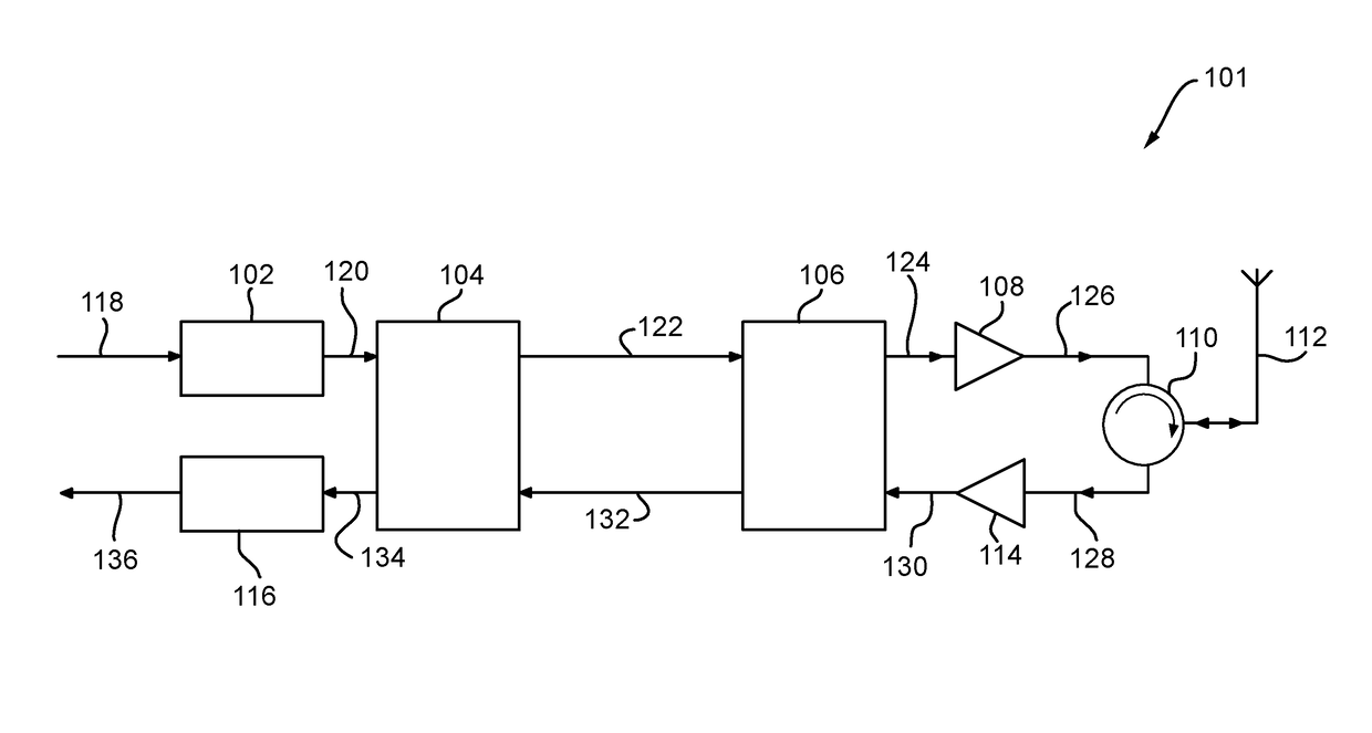
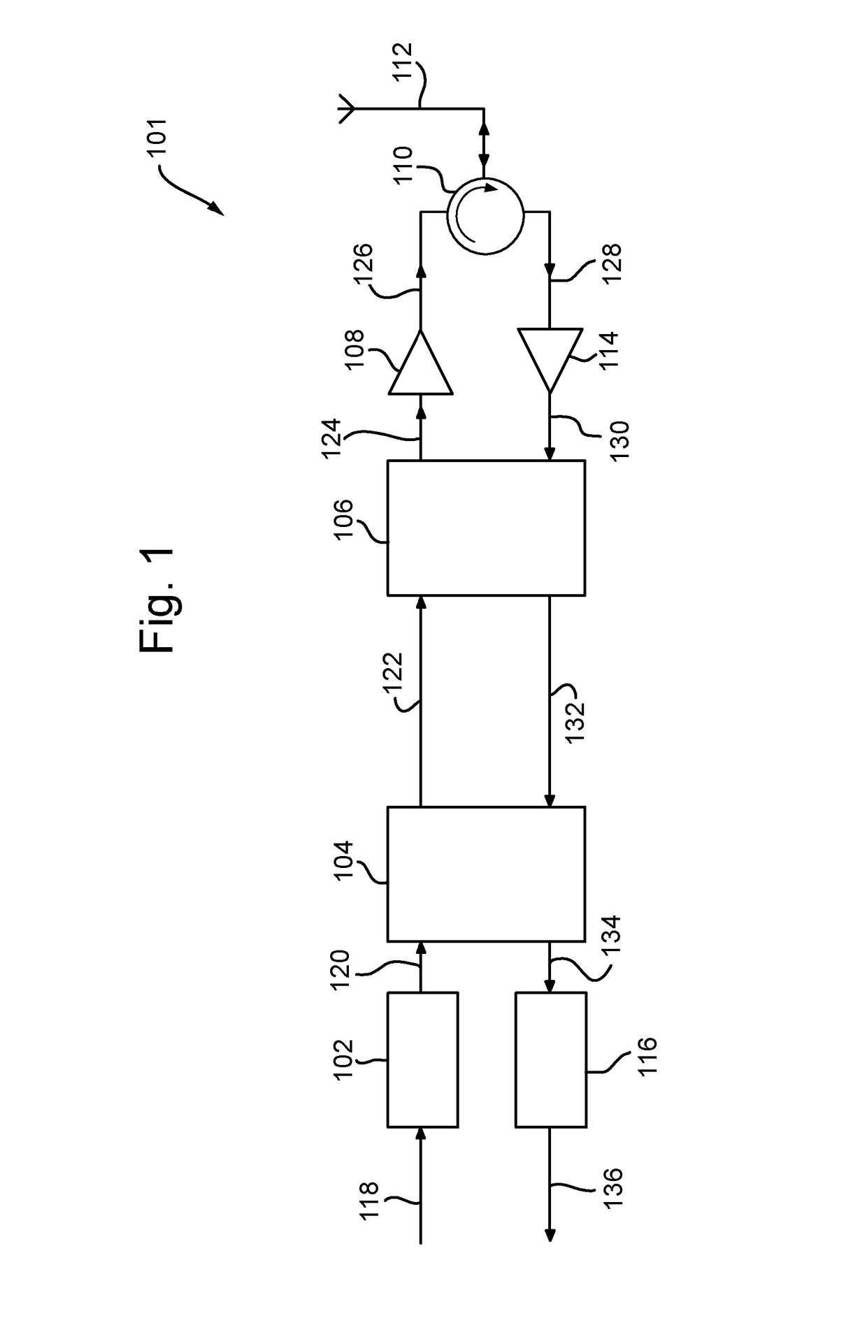
[0042]FIG. 1 is a schematic illustration (not to scale) of a signal transmitting / receiving system 101. In this embodiment, the system 101 is implemented on-board (i.e. located within and / or mounted on) an aircraft, as described in more detail later below.

[0043]The system 101 comprises a transmit signal processing module 102, a first optical-electrical conversion module 104 (hereinafter referred to as the “first optical module”), a second optical-electrical conversion module 106 (hereinafter referred to as the “second optical module”), a power amplifier 108, an electrical circulator 110, an antenna 112, a low-noise amplifier 114, and a receive signal processing module 116.

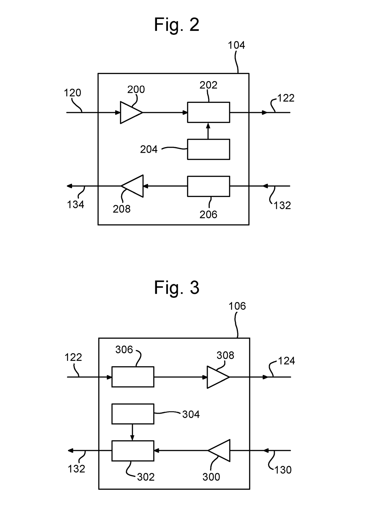
[0044]What will now be described is an example operation of transmitting and receiving signals by the system 101. The couplings and connections between the modules and elements of the system 101 will also be described. In the below description, reference is made to FIG. 2, which shows further details of the first op...

second embodiment

[0082]What will now be described is a signal transmitting / receiving system, hereinafter referred to as the “further system”, in which a single optical fibre that provides both transmit and receive channels for multiple antennas.

[0083]FIG. 5 is a schematic illustration (not to scale) of the further system 501. In this embodiment, the system 501 is implemented on-board the aircraft 400, as described in more detail later below. In the Figures, like reference numerals designate like parts.

[0084]The further system 501 comprises the modules and connections of four of the systems depicted in FIG. 1 and described above. The four systems 101 are coupled together as described in more detail later below to provide four transmit / receive channels.

[0085]In this embodiment, in addition to the modules and connections of four individual systems 101, the further system comprises a first wavelength division multiplexer / de-multiplexer 502 (hereinafter, the “first WDM”), a second wavelength division mul...

third embodiment

[0120]In this third embodiment, the signal transmitting / receiving system is implemented on the aircraft 400.

[0121]FIG. 6 is a schematic illustration (not to scale) showing modules and apparatus located at the equipment bay 416 in the third embodiment. The modules and apparatus shown in FIG. 6 are hereinafter collectively referred to as the “equipment bay modules” and indicated using the reference numeral 601.

[0122]FIG. 7 is a schematic illustration (not to scale) showing modules and apparatus located at the wing bays 418 in the third embodiment. The modules and apparatus shown in FIG. 7 are hereinafter collectively referred to as the “wing bay modules” and indicated using the reference numeral 701.

[0123]In this third embodiment, the wing bay modules 701 including the antennas 112a-d are configured to operate with RF signals within all of the four communication bands (BANDS 1-4). Thus, the wing bay modules 701 in this third embodiment may be wider bandwidth than those used in, for ex...


PUM


Abstract

Signal processing apparatus located in and/or mounted on an entity (e.g. an aircraft), the signal processing apparatus comprising: a first module; a second module connected to the first module such that signals may be sent between those modules; one or more amplifiers configured to amplify signals sent between the modules; and one or more optical fibres. The first module is located at a first location in/on the entity. The second module and the one or more amplifiers are located at a second location in/on the entity. The first location and the second location are spatially separate, i.e. remote from one another. The optical fibre(s) couple together the first and the second locations such that a signal sent between those locations is sent via the optical fibre(s).

Description

FIELD OF THE INVENTION[0001]The present invention relates to signal processing apparatus and in particular signal processing apparatus that is mounted wholly on and / or in an entity, for example, a vehicle.BACKGROUND[0002]Many aircraft, including unmanned aircraft, utilise a number of communication and data link systems to enable them to operate effectively.[0003]Typically, these systems include one or more signal transceivers connected to one or more antennas.[0004]The transceivers tend to be located within in a fuselage of the aircraft, for example, in a central equipment bay.[0005]Also, the antennas of the aircraft tend to be located at or proximate to extremities of the aircraft, for example, at or proximate to the aircraft wing tips. This tends to reduce or eliminate signal blocking by the body of the aircraft.[0006]The transceivers are usually connected to the antennas via electrical conductive cables such as coaxial cable. Such coaxial cable tends to be heavy. Also, signals ca...

Claims


Application Information

Patent Timeline
Patent Type & Authority Applications(United States)
IPC IPC(8): H04B10/2575B64F5/60
CPCB64F5/60H04B10/2575H04B1/3822H04B10/807
Inventor PESCOD, CHRISTOPHER RALPHNAWAZ, MOHAMMEDHARPER, COLIN JAMES
Owner BAE SYSTEMS PLC
Why Eureka
Try Eureka