Closing a chamber of a container for a pharmaceutical product

Active Publication Date: 2017-09-14
F HOFFMANN LA ROCHE & CO AG
View PDF18 Cites 6 Cited by
  • Summary
  • Abstract
  • Description
  • Claims
  • Application Information

AI Technical Summary

Benefits of technology

[0037]In another variant of the second preferred embodiment, the holder part of the spacer comprises an inclined ramp and the support part of the spacer comprises a slider, wherein the slider is movable along the ramp from the distant position in which the plunger seat of the support is distant and laterally displaced from the container carrier of the holder to the near position in which the plunger seat of the support is adjacent and straightly directed to the container carrier of the holder. The ramp can have a straight or bent surface along which the slider can move while being in contact. The term “inclined” can relate to a slant inclination of the ramp with respect to a direction the support and the holder have to be moved to each other in order in order to bring the plunger and the opening of the container together. The slider can comprise or be shaped as a post or a similar structure suitable for moving in contact with and along the ramp. The ramp and the slider allow for precisely moving the support and the holder towards each other wherein this movement is not in a straight direction but in a in direction sideways or laterally to each other. Thus, the ramp allows for moving the support and the holder towards each other and at the same time laterally offsetting the support and the holder to each other.
[0038]Thereby, the holder part of the spacer comprises a distant fastener at one end of the ramp for fastening the slider of the support part of the spacer in the distant position and a near fastener at the other end of the ramp for fastening the slider of the support part of the spacer in the near position. The distant fastener can, e.g., be embodied as a hook clamping the slider when the holder is in the distant position. The near fastener can, e.g., be formed as a recess in which the s

Problems solved by technology

However, namely on an industrial level the closing of containers in a sterile manner when preparing the containers comprising the pharmaceutical can be cumbersome and cause an undesirable effort.
In particular, closing containers in the process of preparing lyophilized pharmaceuticals inside the containers can b

Method used


Image

  • Closing a chamber of a container for a pharmaceutical product
  • Closing a chamber of a container for a pharmaceutical product
  • Closing a chamber of a container for a pharmaceutical product

Examples


first embodiment

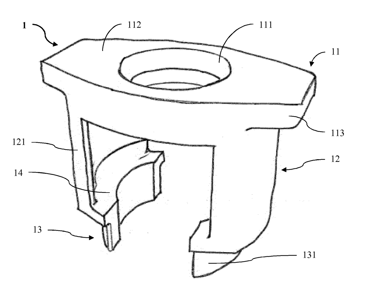
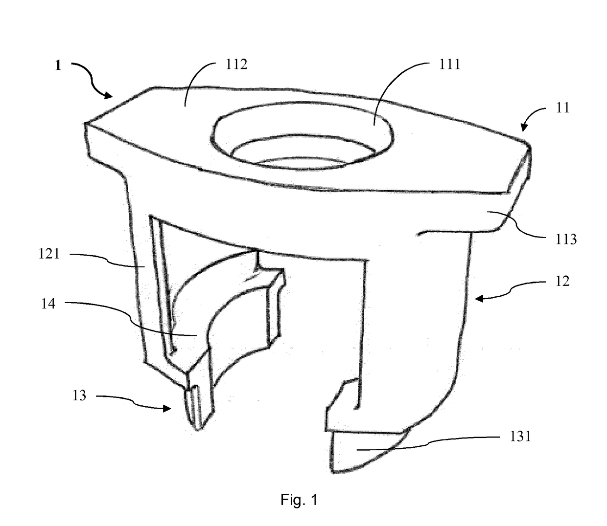
[0061]In FIG. 1 a device 1 according to the invention is shown. The device 1 comprises a support with a plunger seat 11, a container connector 13 as container carrier and a spacer 12 between the plunger seat 11 and the container connector 13. The support is embodied as one piece made from a plastic material. The plunger seat 11 is formed as a longitudinal plate 112 of a constant thickness having plane top and bottom surfaces. In a top view the longitudinal plate 112 widens towards its middle such that a central section of the plate 112 has the largest width. In this central section of the longitudinal plate 112 a central through-hole 111 is arranged.

[0062]On its bottom surface the longitudinal plate 112 passes over into the spacer 12. The spacer 12 comprises two opposing cylinder segments 121. The cylinder segments 121 surround a circular cylindrical interior. Each of the two lateral sections of the longitudinal plate 112 form a protrusion 113 laterally projecting over the spacer 12...

second embodiment

[0083]In FIG. 3 a device 10 according to the invention is shown. The device 10 comprises a support with a plunger seat 110, a container connector 130 as container carrier and a spacer 120 between the plunger seat 110 and the container connector 130. The support is embodied as one piece made from a plastic material. The plunger seat 110 is formed as a longitudinal plate 1120 of a constant thickness having plane top and bottom surfaces. In a top view the longitudinal plate 1120 widens towards its middle such that a central section of the plate 1120 has the largest width. In this central section of the longitudinal plate 1120 a central through-hole 1110 is arranged.

[0084]On its bottom surface the longitudinal plate 1120 passes over into the spacer 120. The spacer 120 comprises a hollow cylinder segment 1210 radially extending over about 270°. The cylinder segment 1210 surrounds a circular cylindrical interior. Each of two lateral sections of the longitudinal plate 1120 laterally projec...

third embodiment

[0104]In FIG. 5 a device 18 according to the invention is shown. The device 18 comprises a holder 118 and a support 128. The holder 118 has an essentially squared holder base plate 1118 equipped with ten rows of ten syringe cavities 1128 as container carriers wherein each two neighbouring rows are offset to each other. Each syringe cavity 1128 is built as a vertical hollow cylinder extending from the holder base plate 1118. In order to stabilize the arrangement of the syringe cavities 1128 their cylinders are interconnected by ridges 1148. The holder 118 is arranged for providing a plurality of nested syringes.

[0105]Laterally beside the syringe cavities 1128 hollow cylinders of holder parts 1138 of spacers vertically extend from the base plate 1118 of the holder 118. In particular, two holder parts 1138 of the spacers are located near each of the sides of the base plate 1118 such that the holder 118 is equipped with eight holder parts 1138.

[0106]The support 128 comprises an essentia...


PUM

PropertyMeasurementUnit
Diameteraaaaaaaaaa
Distanceaaaaaaaaaa

Abstract

A device (1) for closing a chamber of a container having an opening for accessing the chamber comprises a plunger, a plunger seat (11), a container carrier (13) and a spacer (12). The plunger seat (11) releasably holds the plunger in a predefined alignment. The container carrier (13) is arranged to be connected to the container in a predefined position and alignment in relation to the opening of the container. The spacer (12) is arranged to position and align the plunger seat (11) adjacent to and distant from the container carrier (13) such that the opening of the container is open when the container is connected to the container carrier (13).

Description

TECHNICAL FIELD[0001]The present invention relates to a device for closing a chamber of a container having an opening for accessing the chamber. Such devices can be used in processes of preparing pharmaceutical products and containers filled with pharmaceutical products.BACKGROUND ART[0002]Many pharmaceutical products, pharmaceutical substances or simply pharmaceuticals are processed and / or applied in liquid form. For this, the liquid pharmaceuticals are filled into containers such as in vials, syringes or the like. Also, many pharmaceuticals and particularly biopharmaceuticals which frequently are highly unstable in liquid form are often provided in a lyophilized form in which they are essentially more stable and robust compared to their liquid forms. The lyophilized pharmaceuticals can also be filled and provided in containers. Before being applied to patients, they are reconstituted or solved in a diluent or similar liquid.[0003]For allowing injection such as subcutaneous, intram...

Claims


Application Information

Patent Timeline
IPC IPC(8): B65B7/28B65D25/10B65D51/00B65B55/02B65B3/00B65B63/08
CPCB65B7/2821B65B3/003B65D25/108B65D51/00B65B55/027B65B63/08B67B1/04A61M5/008
Inventor WERK, TOBIASLUMKEMANN, JORGMAHLER, HANNS-CHRISTIANKISSLING, TOM
Owner F HOFFMANN LA ROCHE & CO AG
Why Eureka
Try Eureka