Heat Exchanger, Use of an Aluminium Alloy and of an Aluminium Strip as well as a Method for the Production of an Aluminium Strip

a technology of heat exchanger and aluminium alloy, which is applied in the direction of manufacturing tools, soldering devices, light and heating equipment, etc., can solve the problems of difficult control of the distribution of zinc in the brazed heat exchanger, high concentration of zinc within the brazed connection between the mpe and the manifold, and environmental influences that affect the performance of the heat exchanger. , to achieve the effect of low corrosion potential, good strength and low corrosion potential

Inactive Publication Date: 2017-09-14
HYDRO ALUMINIUM ROLLED PROD GMBH
View PDF0 Cites 7 Cited by
  • Summary
  • Abstract
  • Description
  • Claims
  • Application Information

AI Technical Summary

Benefits of technology

[0109]An aluminium alloy with good strength and simultaneously sufficiently low corrosion potential is thereby achieved.
[0110]According to a further embodiment, the component connected to the exchanger tube is a manifold or a tubesheet. In heat exchangers, exchanger tube are typically connected directly to manifolds or to tubesheets such that these components form a direct galvanically coupled corrosion system with the exchanger tubes. A manifold or a tubesheet with lower corrosion potential than the exchanger tube is consequently well suited to anodically protect the exchanger tube.

Problems solved by technology

Corrosion by environmental influences poses a significant problem in brazed heat exchangers of aluminium, in particular for applications in the automobile field.
However, the previously mentioned measures have the disadvantage that the distribution of the zinc in the brazed heat exchanger is difficult to control.
In unfavourable cases, a high concentration of zinc within the brazed connections between the MPE and the manifold or also between the MPE and a cooling fin may occur as a result.
As a result, these brazed connections may become the most anodic region of the heat exchanger, i.e. the region with the lowest corrosion potential, and thus preferably corrode which may lead to a high performance loss of the heat exchanger (in the case of corrosion of the brazed connection between MPE and cooling fin) or even to the failure of the heat exchanger (in the case of corrosion of the brazed connection between MPE and manifold).
However, this requires significant effort and prevents the use of standardised materials.

Method used


Image

  • Heat Exchanger, Use of an Aluminium Alloy and of an Aluminium Strip as well as a Method for the Production of an Aluminium Strip
  • Heat Exchanger, Use of an Aluminium Alloy and of an Aluminium Strip as well as a Method for the Production of an Aluminium Strip
  • Heat Exchanger, Use of an Aluminium Alloy and of an Aluminium Strip as well as a Method for the Production of an Aluminium Strip

Examples


Embodiment Construction

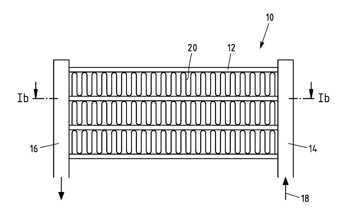
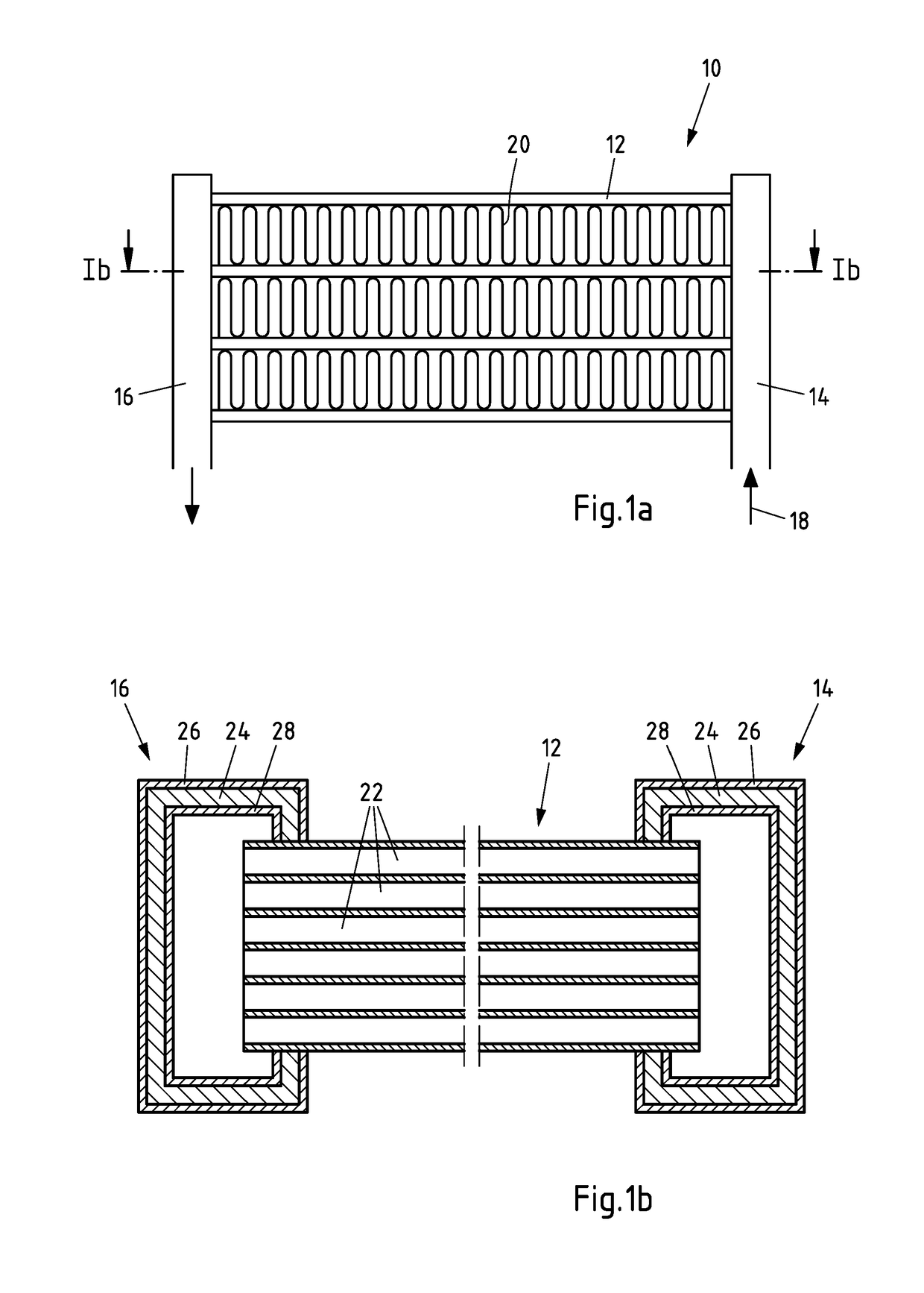
[0173]FIGS. 1a and 1b show an exemplary embodiment of the heat exchanger as well as the use of an aluminium alloy or an aluminium strip. FIG. 1a shows a schematic side view of the heat exchanger and FIG. 1b shows a section through the plane designated in FIG. 1a with “1b”.

[0174]The heat exchanger 10 has a plurality of exchanger tubes 12, whose ends are in each case connected to a first manifold 14 as well as to a second manifold 16. The manifolds 14, 16 thus in each case constitute a component connected to the exchanger tubes 12.

[0175]A medium flow 18 is introduced into the first manifold 14 during operation which is distributed to the exchanger tubes 12 and lastly flows through the manifold 16 out of the heat exchanger 10 again. A second medium flow flows towards the region of the exchanger tubes 12 during operation, said second medium flow comes into thermal contact with the outer surface of the exchanger tubes 12 as a result, such that a heat exchange occurs between the first an...


PUM

PropertyMeasurementUnit
corrosion potentialaaaaaaaaaa
temperatureaaaaaaaaaa

Abstract

Provided is a heat exchanger, in particular for motor vehicles, with at least one exchanger tube of an aluminium alloy and with at least one component connected fluidically to the exchanger tube, wherein the exchanger tube and the component (14, 16) are connected to one another by way of a common soldered connection and wherein the component connected to the exchanger tube has a core layer of an aluminium alloy with the following composition: Si: max. 0.7% by weight, Fe: max. 0.70% by weight, Cu: max. 0.10% by weight, Mn: 0.9-1.5% by weight, Mg: max. 0.3% by weight, Cr: max. 0.25% by weight, Zn: max. 0.50% by weight, Ti: max. 0.25% by weight, Zr: max. 0.25% by weight, unavoidable impurities individually max. 0.05% by weight, altogether max. 0.15% by weight, the remainder aluminium.

Description

CROSS-REFERENCE TO RELATED PATENT APPLICATIONS[0001]This patent application is a continuation of PCT / EP2015 / 077653, filed Nov. 25, 2015, which claims priority to German Application No. 10 2014 117 384.8, filed Nov. 27, 2014, and European Application No. 15158514.8, filed Mar. 10, 2015, the entire teachings and disclosure of which are incorporated herein by reference thereto.FIELD OF THE INVENTION[0002]The invention relates to a heat exchanger, in particular for motor vehicles, with at least one exchanger tube made of an aluminium alloy and with at least one component connected in fluid communication to the exchanger tube, wherein the exchanger tube and the component are connected to one another by way of a common brazed connection. The invention also relates to the use of an aluminium alloy or of an aluminium strip with a core layer of this aluminium alloy for the production of a manifold or a tubesheet for a brazed heat exchanger as well as a method for the production of a roll-cla...

Claims


Application Information

Patent Timeline
Patent Type & Authority Applications(United States)
IPC IPC(8): C22F1/043B22D7/00B23K35/28F28F21/08F28D1/02F28D1/053F28F1/02F28F1/12C22C21/02B23K1/00
CPCC22F1/043C22C21/02B22D7/005B23K35/288B23K1/0012F28F2275/04F28D1/05383F28F1/022F28F1/126F28F21/084F28D1/0233B23K35/00C22C21/00C22F1/04
Inventor JANSSEN, HARTMUTBERMIG, GERHARDSAVOLKERSCHLUTER, STEFAN
Owner HYDRO ALUMINIUM ROLLED PROD GMBH
Why Eureka
Try Eureka