Centrifugal compressor with casing treatment bypass

a centrifugal compressor and bypass technology, which is applied in the direction of machines/engines, liquid fuel engines, light and heating apparatus, etc., can solve the problems of affecting affecting the operation of the compressor, and the ability of the compressor to maintain its lift, etc., to achieve the effect of increasing the operation range of the compressor, increasing the cost, and increasing the specific volume of the refrigeran

Inactive Publication Date: 2017-09-14
DAIKIN APPLIED AMERICAS
View PDF8 Cites 30 Cited by
  • Summary
  • Abstract
  • Description
  • Claims
  • Application Information

AI Technical Summary

Benefits of technology

[0009]In a conventional centrifugal compressor as shown in FIG. 10, a hot gas bypass may be provided to connect the discharge side of the compressor and the suction side of the compressor to expand the operation range of the compressor. While this technique works relatively well, this system requires a pipe of a large diameter for the hot gas bypass, which results in increased costs. Especially in a case where a centrifugal compressor uses low pressure refrigerant such like R1233zd, the specific volume of the refrigerant is large compared to a case of conventional refrigerant such like R134a. This requires a large-diameter pipe for the hot gas bypass, which results in increased costs.

Problems solved by technology

The compressor loses the ability to maintain its lift when surge occurs and the entire system becomes unstable.
Surging can cause damage to the mechanical impeller / shaft system and / or to the thrust bearing due to the rotor shifting back and forth from the active to the inactive side.
While this technique works relatively well, this system requires a pipe of a large diameter for the hot gas bypass, which results in increased costs.
This requires a large-diameter pipe for the hot gas bypass, which results in increased costs.

Method used


Image

  • Centrifugal compressor with casing treatment bypass
  • Centrifugal compressor with casing treatment bypass
  • Centrifugal compressor with casing treatment bypass

Examples


Embodiment Construction

)

[0026]Selected embodiments will now be explained with reference to the drawings. It will be apparent to those skilled in the art from this disclosure that the following descriptions of the embodiments are provided for illustration only and not for the purpose of limiting the invention as defined by the appended claims and their equivalents.

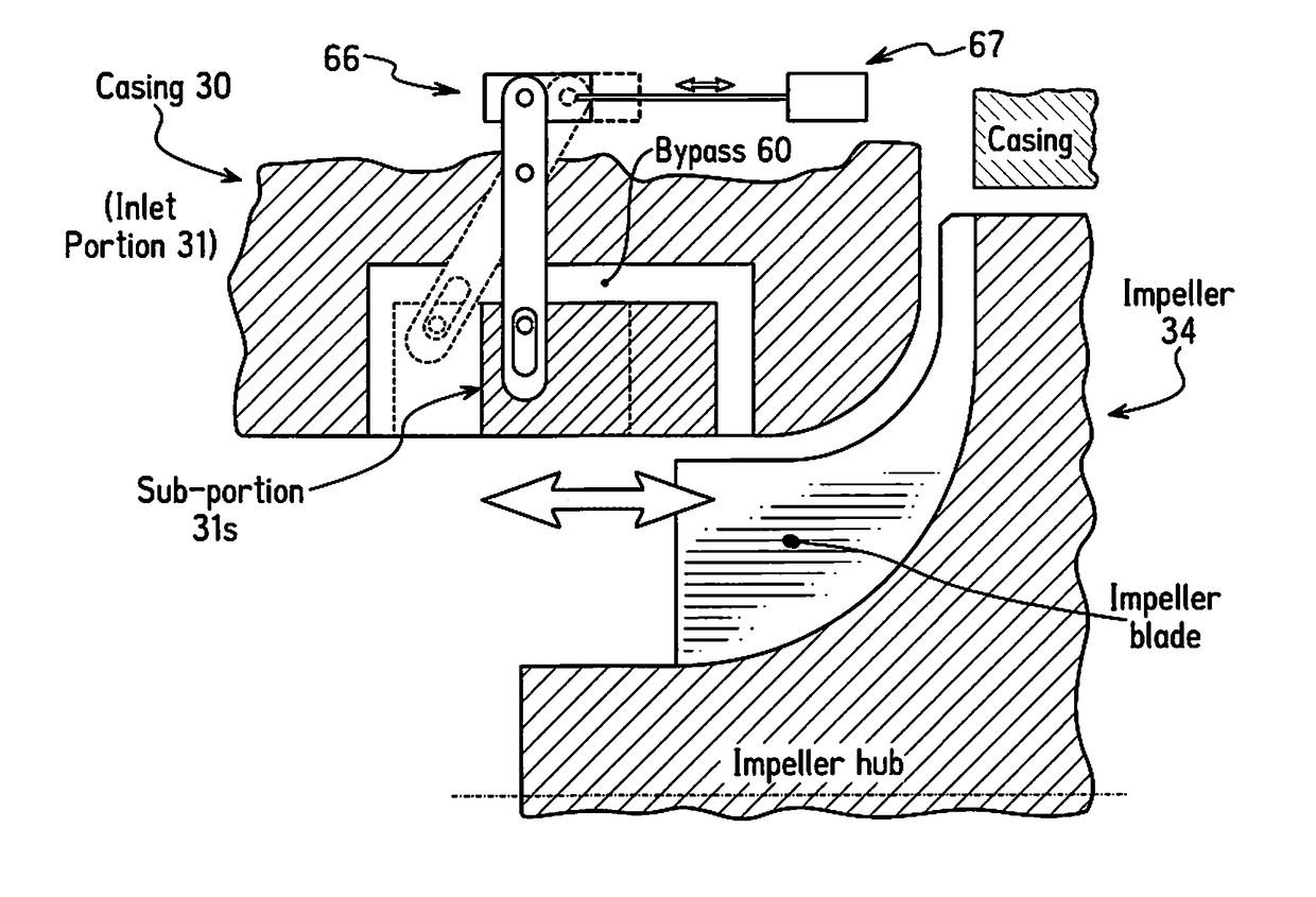
[0027]Referring initially to FIG. 1, a chiller system 10, which includes a casing treatment bypass 60 (60a, 60b), is illustrated in accordance with an embodiment of the present invention. The chiller system 10 is preferably a water chiller that utilizes cooling water and chiller water in a conventional manner. The chiller system 10 illustrated herein is a two-stage chiller system. However, it will be apparent to those skilled in the art from this disclosure that the chiller system 10 could be a single stage chiller system or a multiple stage chiller system including three or more stages.

[0028]The chiller system 10 basically includes a chiller con...


PUM


Abstract

A centrifugal compressor for a chiller system includes a casing, an inlet guide vane, an impeller disposed downstream of the inlet guide vane, a motor and a diffuser. The casing has inlet and outlet portions with the inlet guide vane disposed in the inlet portion. The impeller is attached to a shaft rotatable about a rotation axis, and the motor rotates the shaft in order to rotate the impeller. The centrifugal compressor further includes a casing treatment bypass having an entrance port and an exit port. The casing treatment bypass injects refrigerant from a gap between the impeller and the inlet portion of the casing toward an area between the impeller and the inlet guide vane. The exit port of the casing treatment bypass is positioned upstream in a direction of a refrigerant flow with respect to the entrance port of the casing treatment bypass.

Description

BACKGROUND[0001]Field of the Invention[0002]The present invention generally relates to a centrifugal compressor used in a chiller system. More specifically, the present invention relates to a centrifugal compressor with a casing treatment bypass.[0003]Background Information[0004]A chiller system is a refrigerating machine or apparatus that removes heat from a medium. Commonly a liquid such as water is used as the medium and the chiller system operates in a vapor-compression refrigeration cycle. This liquid can then be circulated through a heat exchanger to cool air or equipment as required. As a necessary byproduct, refrigeration creates waste heat that must be exhausted to ambient or, for greater efficiency, recovered for heating purposes. A conventional chiller system often utilizes a centrifugal compressor, which is often referred to as a turbo compressor. Thus, such chiller systems can be referred to as turbo chillers. Alternatively, other types of compressors, e.g. a screw comp...

Claims


Application Information

Patent Timeline
Patent Type & Authority Applications(United States)
IPC IPC(8): F04D27/02F04D29/44F25B49/02F04D29/28F25B1/10F25B31/02F04D29/42F04D29/46
CPCF04D27/0215F04D29/4206F04D29/444F04D29/462F25B49/022F04D27/0246F25B1/10F25B31/026F04D29/284F04D29/4213F04D29/685
Inventor ONODERA, FUMIAKI
Owner DAIKIN APPLIED AMERICAS
Why Eureka
Try Eureka