
Pressure Compensated Flow Tube for Deep Set Tubular Isolation Valve

a technology of flow tube and isolation valve, which is applied in the direction of valve operating means/release devices, sealing/packing, and borehole/well accessories, etc., can solve the problems of affecting the operation of the valv

Active Publication Date: 2017-09-14
BAKER HUGHES INC
View PDF0 Cites 4 Cited by
  • Summary
  • Abstract
  • Description
  • Claims
  • Application Information

AI Technical Summary

Benefits of technology

The invention is about a subsurface safety valve that can be used in underwater wells. The valve has a sealed space around it and is pressure compensated, meaning it can withstand the pressure of the sea water. The valve is designed to be easily installed and can handle the harsh conditions of underwater environments without needing major adjustments. It also has a position indicating device that lets people know where it is located. The device uses hydraulic pressure to move a piston, which causes a visual indicator to move. This makes it easy to control the valve and keep sea water away from the indicator.

Problems solved by technology

Traditional flapper style subsurface safety valves are known to suffer from debris related issues in downhole production environments.
These issues can come in various forms and can range from mechanical fouling, caused by the accumulation of sand in the annular spring cavity, to piston or flow tube sticking caused by the solidification of heavy asphaltene or paraffin formations in the same region.
Issues such as these can be extremely costly to operators given that their mitigation traditionally requires an intervention, at a minimum, and often times a full work-over to pull and replace the valve and / or completion.
In the context of isolation valves for use within subsea production environments (i.e. installations within subsea production risers), the threat of debris fouling is exponentially increased.
This debris problem requires routine remedial activity in the form of round trip “pigging” to scrape the I.D. of the Riser and clear solid deposits from its flow path.
Because of the high operating pressures and the line sizes involved these valves are extremely heavy and have a fairly large profile exposed to wave and underwater current action.

Method used


Image

  • Pressure Compensated Flow Tube for Deep Set Tubular Isolation Valve
  • Pressure Compensated Flow Tube for Deep Set Tubular Isolation Valve
  • Pressure Compensated Flow Tube for Deep Set Tubular Isolation Valve

Examples


Embodiment Construction

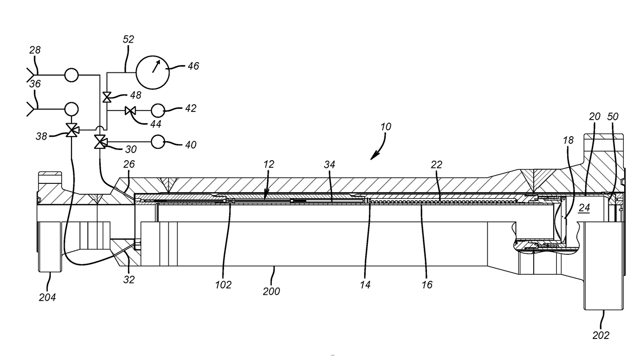
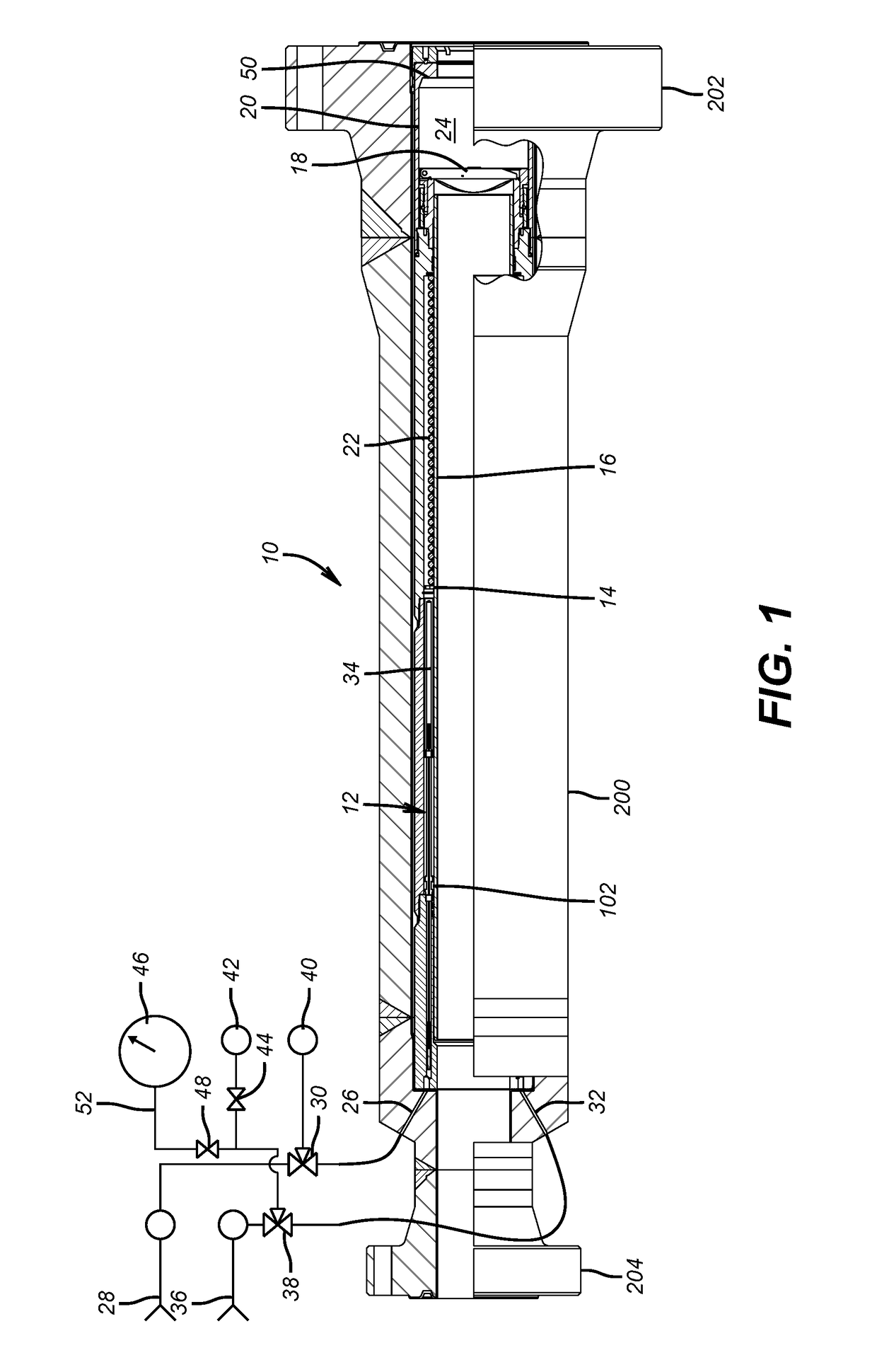
[0029]FIG. 1 shows an isolation valve located subsea inside a housing 200 that has opposed flanged ends 202 and 204 associated with a riser leading to an adjacent platform that are not shown. The housing 200 allows the use of a borehole safety valve in a subsea application where threaded connections that are typically used on borehole safety valves is not permitted. The isolation valve 10 can be taken as used in a borehole and put in a housing 200 and flanged to a marine riser to present advantages of weight savings and a low profile to minimize the drag resulting from underwater currents which plagues the existing style of hydraulically actuated ball valves typically used in this service. Control lines 28 and 36 sealingly connect to connections 26 and 32 of the isolation valve 10 through the housing 200. Internally, the isolation valve 10 is a known design with an operating hydraulic piston assembly 12 connected to an upset 102 on a flow tube 16. Movement of the flow tube 16 agains...


PUM


Abstract

The annular space surrounding a flow tube in a subsurface safety valve is sealingly isolated at opposed ends of the flow tube and pressure compensated to the tubing pressure. The subsurface safety valve is inserted and aligned in an outer housing so that hydraulic operating connections are sealingly aligned with opposite hand split ring seals that are properly compressed when the safety valve is secured in its surrounding housing. The assembly is then able to meet high pressure, heavy debris, and marine environment service requirements for subsea conditions with minimal reconfiguration for what would otherwise serve as a borehole subsurface safety valve.

Description

FIELD OF THE INVENTION[0001]The field of the invention a flow tube operated flapper type safety valve and more particularly a sealed annular cavity containing the valve's operating system to isolate the system from contact with production fluids and / or solids and thereby increase the reliability and longevity of the system. The field of the invention also includes a pressure compensation system to continually balance the pressure within the sealed annular cavity to the pressure of the internal production fluids within the valve (at any given pressure within valve's operating range). As a result of the pressure compensation system, the hydraulic operating pressures required to function the valve open are greatly reduced due to the pressure balance. As well, the valve's thru-bore size can be increased for maximized production flow rates since the flow tube is no longer designed to withstand a significant pressure differential. Finally the field of the invention includes a load bearing...

Claims


Application Information

Patent Timeline
Patent Type & Authority Applications(United States)
IPC IPC(8): F16K31/122E21B43/12E21B34/10
CPCF16K31/1223E21B2034/005E21B43/12E21B34/10E21B2200/05
Inventor MILLER, WADE A.BURRIS, JOHN E.HAIR, MICHAEL L.
Owner BAKER HUGHES INC
Features
  • Generate Ideas
  • Intellectual Property
  • Life Sciences
  • Materials
  • Tech Scout
  • Unparalleled Data Quality
  • Higher Quality Content
  • 60% Fewer Hallucinations
Learn More