Rotary actuator, and beverage filling system

a technology of actuators and actuators, applied in the direction of lift valves, valve details, liquid dispensing, etc., can solve the problems of high specific surface pressure between the bush and the insufficient assembly effort for the required axial securing of the bushes, and early wear, so as to achieve no negative effect on functionality, reduce the contact area in the raceway, and improve the effect of axial securing

Active Publication Date: 2017-09-14
EVOGUARD GMBH
View PDF7 Cites 0 Cited by
  • Summary
  • Abstract
  • Description
  • Claims
  • Application Information

AI Technical Summary

Benefits of technology

[0010]Particularly appropriate, approximately in the middle between both guide groove ends, each guide groove may have a bush assembly opening, which is at least accessible from the outer circumference of the piston. The assembly opening is usable in order to mount at least the bush on the end of the transverse axis or to replace it rapidly in the event of wear, without having to manipulate tools or securing elements. Thereby, the assembly opening is practically placed approximately in the middle between the two guide grooves, thus, in a region of the guide grooves, in which due to the course of the guide grooves the torque to be transmitted is relatively moderate so that there, the problem of the surface pressure between the raceway and the bush is non-critical, although there the contact area in the raceway somewhat decreases.
[0011]The assembly opening is appropriately configured in such a manner that one side of the undercut is removed arcuately in each raceway up to approximately the base of the undercut and corresponding to the contour of the outer circumference of the bush. The temporary lateral interruption of the undercut of the raceway at this point, approximately in the middle between the guide groove ends, has no negative effect on the functionality, since the bushes are moved through this area under relatively moderate load

Problems solved by technology

During operation, however, high specific surface pressure occurs between each bush and the raceways of the guide groove.
The high surface pressure may result in an early wear.
The assembly effort for the required axial securing of the bushes is inappropriate.
Further, during operation, a secure positioning of the bush and an extensive force transfer between larg

Method used


Image

  • Rotary actuator, and beverage filling system
  • Rotary actuator, and beverage filling system
  • Rotary actuator, and beverage filling system

Examples


Embodiment Construction

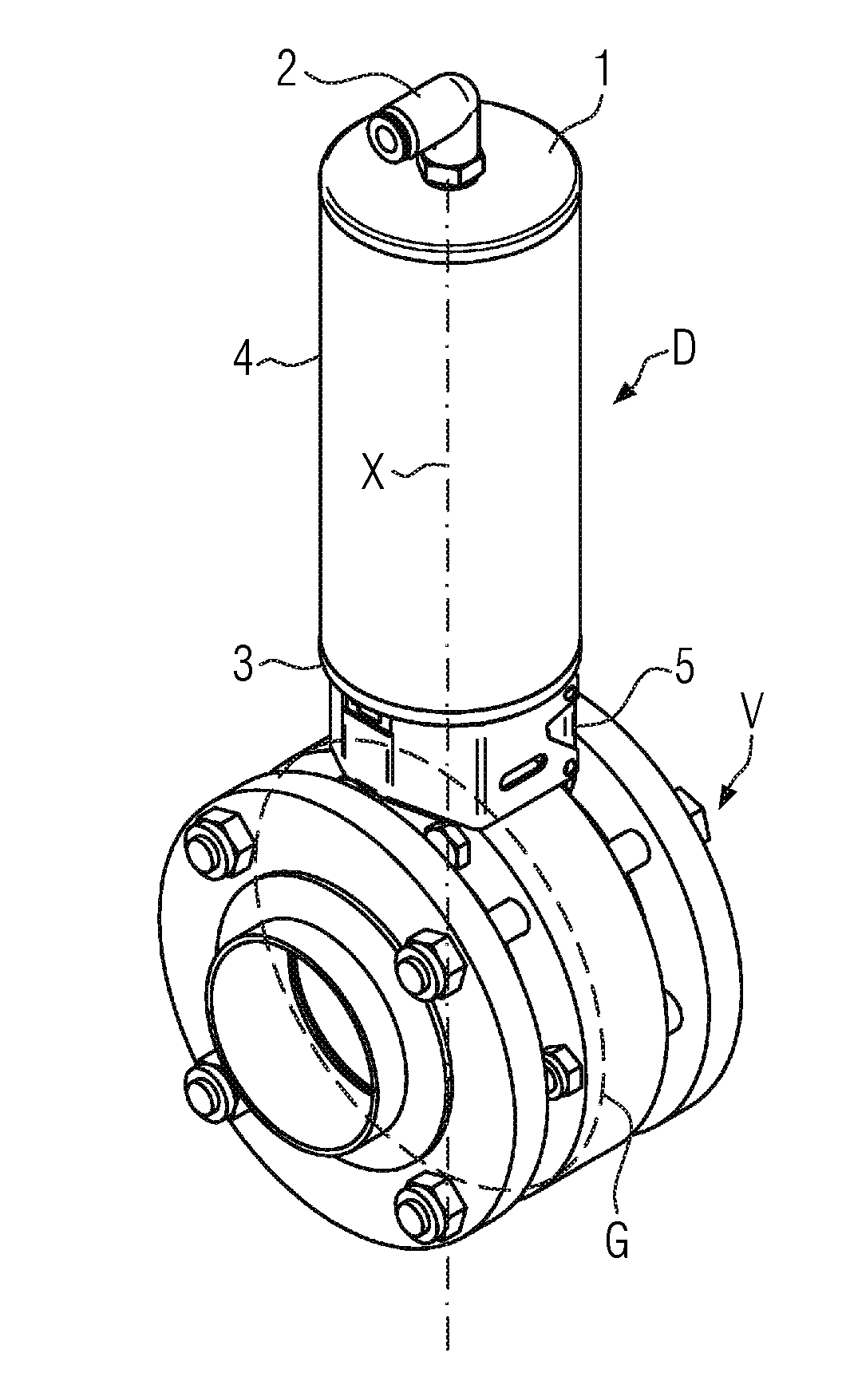
[0022]As non-limiting example, FIG. 1 shows a disk valve V with a closing element G, shown in dashed lines, and which is rotatable back and forth about an axis X, and which can be actuated by means of a rotary actuator D over a pivot angle of, for example, approximately 90° between an open and a closed position. The disk valve V is, for example, installed in a beverage filling system (not shown).

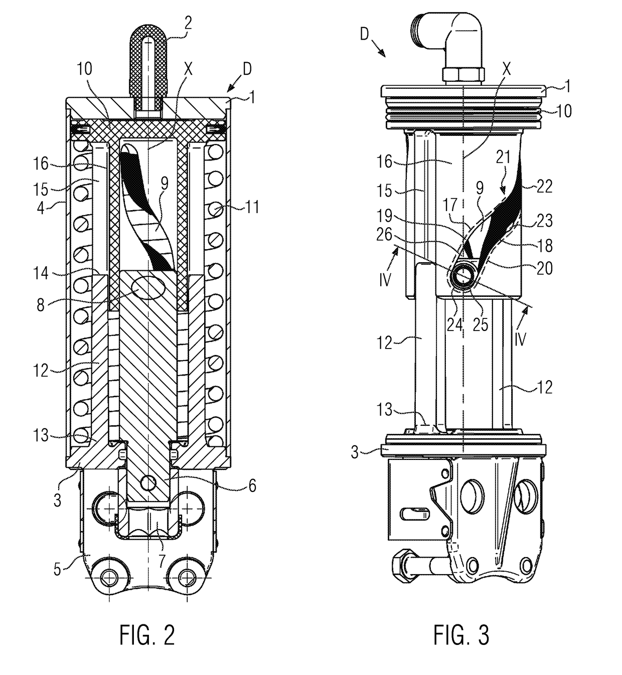
[0023]The rotary actuator D is mounted with a foot part 5 on the disk valve V and comprises a housing 4, here for example cylindrical, with a cover 1 and a base 3. The rotary actuator D here is for example pneumatically actuated via a connection port 2 in the cover 1, for example against a spring, which is not shown in FIG. 1, or electromagnetically actuated by a linear drive, which is not shown (for example even in both actuation directions). In the longitudinal section view in FIG. 2, a shaft 6 is rotatable in the base 3 about the axis X, which extends upwardly into the rotary actuator D a...


PUM


Abstract

In a rotary actuator comprising a housing containing a piston and having a cover and a base, thread-like guide grooves in the piston, a shaft having a transverse axis and being rotatable about an axis of the rotary actuator which transverse axis engages into the guide grooves, and torque support engaging into guides in the piston, which torque supports are anchored in the housing, wherein the transverse axis on both ends comprises bushes contacting raceways of the guide grooves, each bush is cambered and each raceway is configured with an undercut corresponding to the cambering.

Description

CROSS-REFERENCE TO RELATED APPLICATIONS[0001]The present application claims priority to German Patent Application No. 10 2016 203 873.7, entitled “Rotary Actuator, and Beverage Filling System,” filed on Mar. 9, 2016, the entire contents of which are hereby incorporated by reference for all purposes.TECHNICAL FIELD[0002]The present disclosure relates to a rotary actuator and a beverage filling system.BACKGROUND AND SUMMARY[0003]Regarding the rotary actuators known from DE 19950582 C1 and DE 102010002621 A1 for e.g. disk valves in beverage filling systems of this type, the raceways in the guide grooves of the piston are planar and the bushes arranged on the ends of the transverse axis are configured with a cylindrical external circumference. This principle requires positioning the bushes and, if appropriate their bearings on the ends of the transverse axis, for example by means of securing rings or the like so that the bushes during operation of the rotary actuator do not exit e.g. ou...

Claims


Application Information

Patent Timeline
IPC IPC(8): F16K31/528B67D1/00F16K31/122
CPCF16K31/5282B67D2001/0093B67D1/00F16K31/1221F15B15/068F16K1/221F16K31/1635
Inventor JUSTL, JOHANN
Owner EVOGUARD GMBH
Why Eureka
Try Eureka