
Optical up/down conversion-type optical phase conjugate pair signal transmission/reception circuit

a conversion-type, optical phase technology, applied in optics, instruments, radio-over-fibre, etc., can solve the problems of increasing the rf link gain, limiting the light intensity of the optical input to several mw, and becoming impossible to perform linear transmission of the signal, so as to facilitate compensating the non-linear

Active Publication Date: 2017-09-14
NAT INST OF INFORMATION & COMM TECH
View PDF0 Cites 3 Cited by
  • Summary
  • Abstract
  • Description
  • Claims
  • Application Information

AI Technical Summary

Benefits of technology

The invention provides a method and system to easily compensate for the non-linear effects of optical fiber. This helps to improve the quality of optical signal transmission.

Problems solved by technology

In an optical fiber radio system, enhancement of input intensity to an optical fiber leads to an increase of an RF link gain, extension of a transmission distance, and the like, and therefore is an important issue.
However, when the light intensity input to the optical fiber is strengthened, it becomes impossible to perform linear transmission of the signal because it is affected by the non-linear effect caused in the optical fiber.
Thus, the light intensity of optical input is limited to several mW in the current optical fiber radio systems.
However, when the waveform distortion caused by the non-linear effect in an optical transmission path is compensated using the electric circuit, there is a problem that the device becomes complicated, a problem that providings of a plurality of optical modulators using a pre-processed electric signal obtained by digital signal processing or the like for the generation of the optical phase conjugate pair signal becomes necessary on the transmitter side, and a problem that performance of electrical signal processing using digital signal processing or the like becomes necessary on the receiver side.

Method used


Image

  • Optical up/down conversion-type optical phase conjugate pair signal transmission/reception circuit
  • Optical up/down conversion-type optical phase conjugate pair signal transmission/reception circuit
  • Optical up/down conversion-type optical phase conjugate pair signal transmission/reception circuit

Examples


example 1

[0102]Hereinafter, the above-described system will be numerically analyzed. In the following numerical analysis, the analysis is performed using the homodyne C-RoF system. It is assumed that a multilevel signal, such as QPSK and QAM, including a subcarrier of a radio signal is transmitted to a remote location via a standard single-mode fiber. FIG. 17 is a schematic view of the system in the numerical analysis of Example.

[0103]Continuous light is subjected to intensity modulation in a push-pull Mach-Zehnder modulator (MZM), set to a null bias, on a transmitter side, that is, a central station side in the C-RoF system. The MZM performs modulation as follows using an RF signal. A RF sub-carrier signal having a frequency of 10 GHz is subjected to data modulation by an IQ modulation unit, thereby generating a QPSK signal. A symbol rate of this data is 5 GBaud. It is possible to generate a DSB-SC signal, that is, a C-RoF signal using this device. The generated RoF signal has OSNR (in 0.1 ...

example 2

[0107]FIG. 19 is an experimental configuration diagram for validation of a principle of a bias shift-type electro-optical effect phase conjugate signal pair generator. Herein, a compensation effect of a self-phase modulation effect is illustrated based on SMF transmission of 20-Gb / s QPSK. The transmission of the phase conjugate signal pair is performed using the configuration of polarization multiplexing. Continuous light having a wavelength of 1552 nm, output from a fiber laser with a line width of 10 kHz, is branched by the optical coupler on the transmitter side, and the branched beams of light are input to the two independent quadrature modulators, respectively. The quadrature modulators are driven at the same timing using the same I and Q data. A drive signal is an NRZ signal generated by a pulse pattern generator and has a pattern length form of 215-1PRBS. Both secondary Mach-Zehnder modulators of the respective quadrature modulators are set to a null-point bias. The main bias...


PUM

PropertyMeasurementUnit
frequencyaaaaaaaaaa
wavelengthaaaaaaaaaa
total lengthaaaaaaaaaa

Abstract

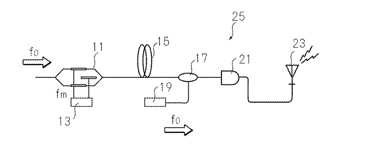
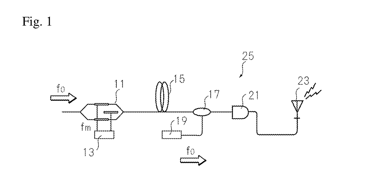
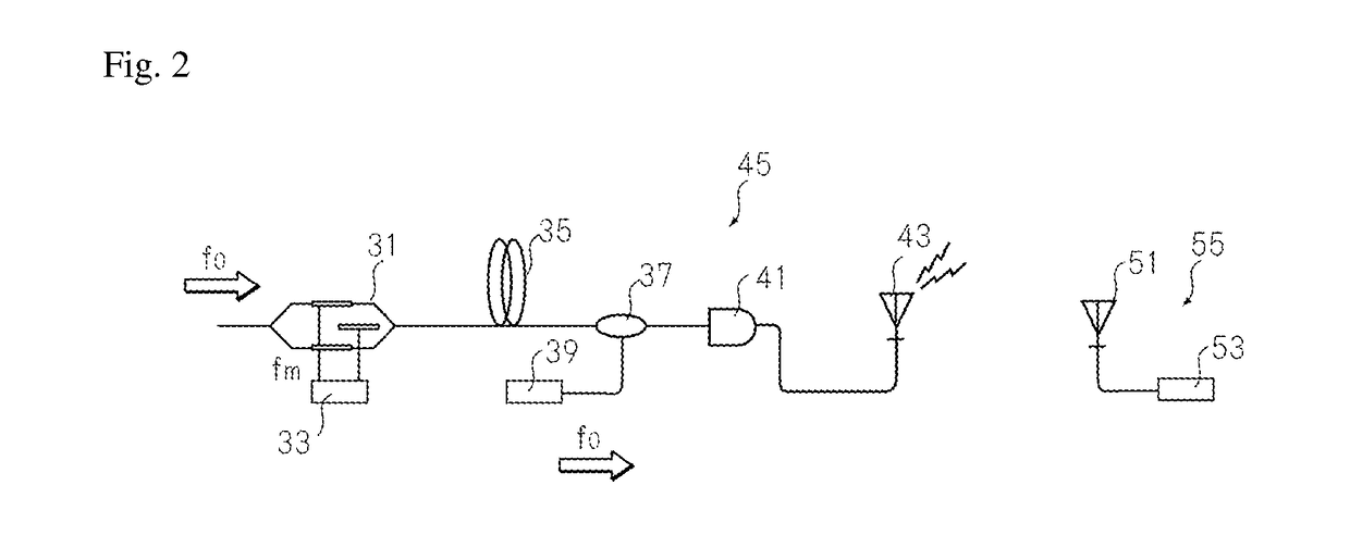
To provide a method capable of easily compensating waveform distortion due to a non-linear effect caused by a complicated electric circuit, and a device for implementing the method. Provided are a method capable of effectively compensating signal degradation such as waveform distortion due to a nonlinear effect caused by an optical fiber that is an optical transfer path using an optical phase conjugate signal pair at the time of optical up-conversion or down-conversion, and a device capable of implementing the method. This emission device 25 includes an optical modulator 11, a signal source 13, an optical fiber 15, a multiplexing unit 17, a multiplexing local signal source 19, an optical detector 12, and a transmission antenna 23.

Description

TECHNICAL FIELD[0001]The present invention relates to a method and a device that can compensate a non-linear effect that is caused when an optical signal and the optical fiber radio signal are transmitted through an optical fiber.BACKGROUND ART[0002]In an optical fiber radio system, enhancement of input intensity to an optical fiber leads to an increase of an RF link gain, extension of a transmission distance, and the like, and therefore is an important issue. However, when the light intensity input to the optical fiber is strengthened, it becomes impossible to perform linear transmission of the signal because it is affected by the non-linear effect caused in the optical fiber. Thus, the light intensity of optical input is limited to several mW in the current optical fiber radio systems.[0003]Meanwhile, complicated optical multiplexing systems such as a coherent optical transmission system of optical phase shift keying (optical PSK), optical quadrature amplitude modulation (optical ...

Claims


Application Information

Patent Timeline
Patent Type & Authority Applications(United States)
IPC IPC(8): H04B10/2507H04B10/516H04B10/58G02F1/225
CPCH04B10/2507G02F1/2255G02F2001/212H04B10/58H04B10/516G02F2/00H04B10/2543H04B10/2575G02F1/212
Inventor SAKAMOTO, TAKAHIDE
Owner NAT INST OF INFORMATION & COMM TECH
Learn More