Control arrangement of a multi-stator machine

a multi-stator machine and control arrangement technology, applied in the direction of control system, electric generator control, generation protection through control, etc., can solve the problems of power converter outage, significant increase in torque ripple, damage to the generator or other components, etc., to improve fault tolerance control, poor performance of a faulty converter, and smooth operation

Active Publication Date: 2017-09-28
SIEMENS GAMESA RENEWABLE ENERGY AS
View PDF5 Cites 9 Cited by
  • Summary
  • Abstract
  • Description
  • Claims
  • Application Information

AI Technical Summary

Benefits of technology

[0009]Each stator of a multiple-stator machine will carry windings for a number of phases, usually three. Therefore, in the context of embodiments of the invention, the term “current value” should be understood to mean current values relating to each of the phases of that stator. For example, a “measurement current” received by a controller can in fact comprises three measured or observed current values, one for each of the phases of a three-phase winding. The “compensation current” in the context of embodiments of the invention is the error between the reference currents and the currents actually observed in a converter. In a healthy converter, these values will generally be quite close. In a faulty converter, at least one pair of reference and observed currents will differ significantly. By exchanging compensation currents in the inventive control method, the error seen in one controller is also “injected” into the controller of a healthy frequency converter. The poor performance of a faulty converter (which would otherwise result in significant torque ripple) is effectively shared with another, healthy frequency converter. The torque ripple caused by the healthy converter can effectively be symmetric to the torque ripple generated by the faulty converter, so that torque ripple arising from an open-circuit fault can advantageously be reduced or even eliminated.
[0010]An advantage of the control arrangement according to embodiments of the invention is that the improved post-fault control of the machine does not require any significant or costly hardware modifications or reconfiguration

Problems solved by technology

A non-switching IGBT—the result of an open-circuit fault in the power switch transistor—is one of the main causes for power converter outage in PMSG wind turbines.
When a power switch fails, the corresponding generator phase currents become distorted or erratic, leading to a significant increase in torque ripple.
While a slight amount of torque ripple is acceptable and indeed even unavoidable during normal fault-free or “healthy” operation of a PMSG, the significantly higher levels of torq

Method used


Image

  • Control arrangement of a multi-stator machine
  • Control arrangement of a multi-stator machine
  • Control arrangement of a multi-stator machine

Examples


Embodiment Construction

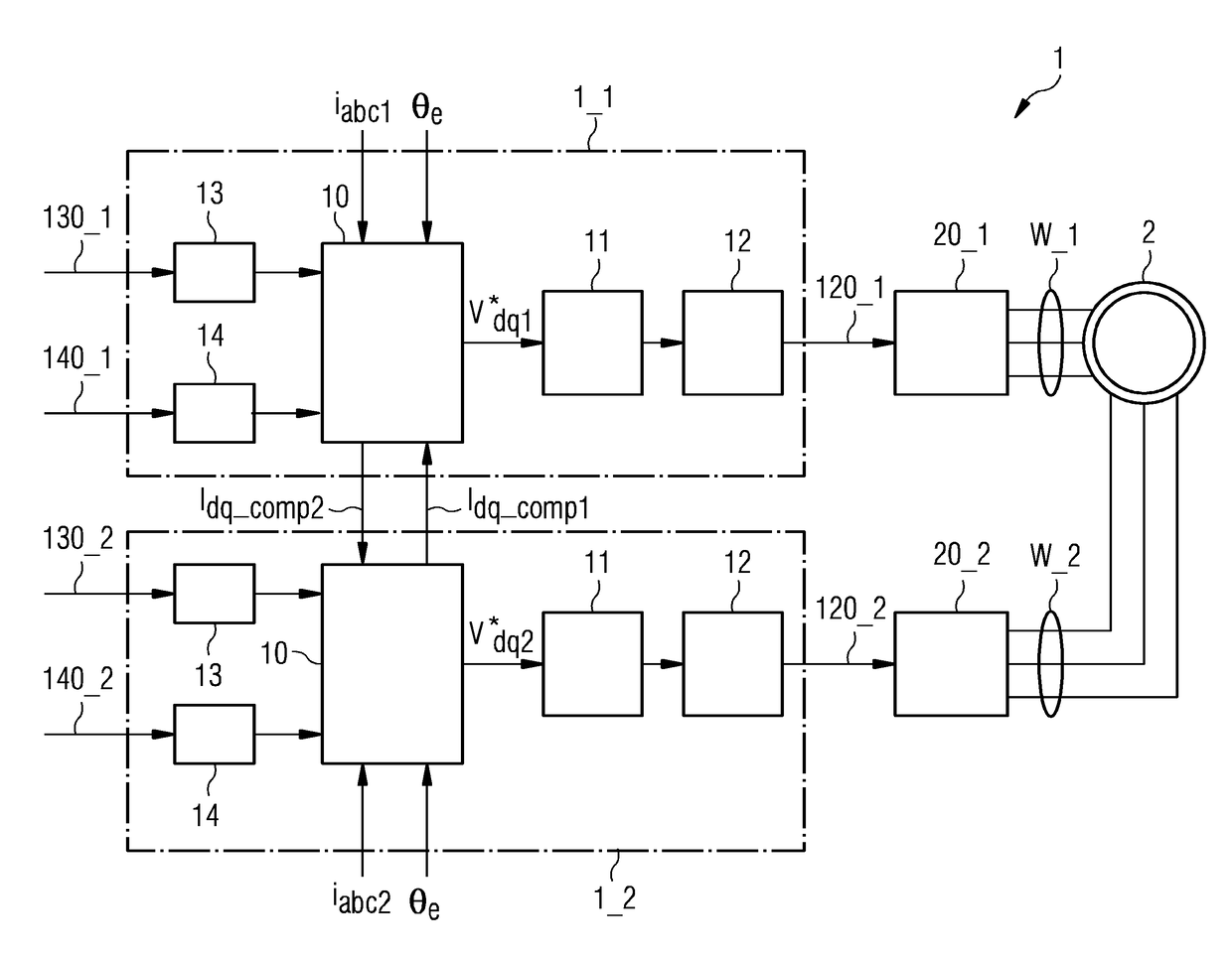
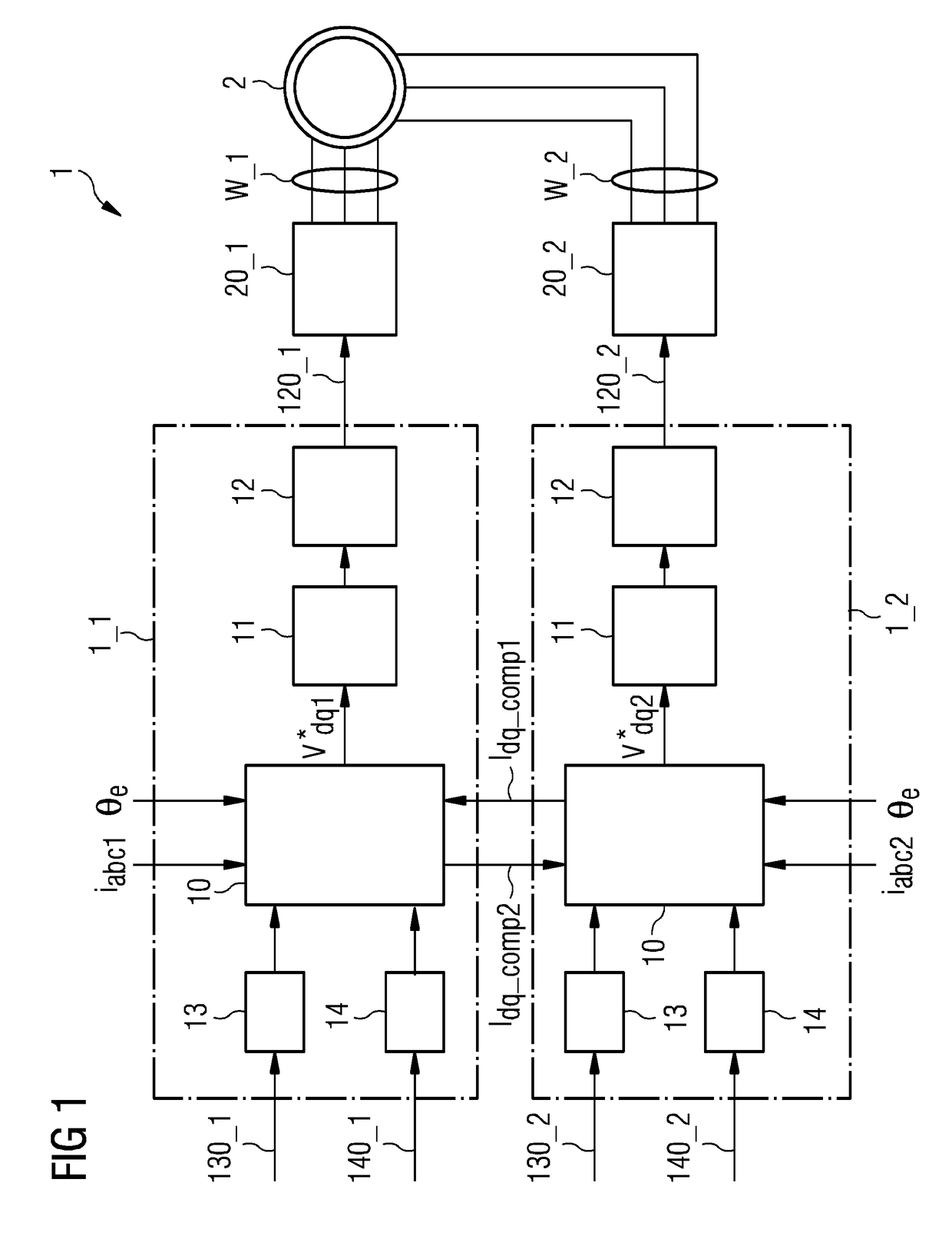
[0042]FIG. 1 shows an embodiment of the control arrangement 1 according to embodiments of the invention in use with a dual-stator PMSG 2. Each of the two stators has a set of windings W_1, W_2. The generator 2 has two frequency converters 20_1, 20_2, one for each stator. Each frequency converter 20_1, 20_2 is controlled by its own controller 1_1, 1_2. Each controller 1_1, 1_2 is supplied with appropriate input signals such as a power reference, rotor position θe, a DC voltage reference, measured values of winding current iabc1, iabc2, generator torque, rotational velocity etc., as will be known to the skilled person. On the basis of various input signals 130_1, 130_2, 140_1, 140_2 an Iq reference computation block 13 and an Id reference computation block 14 determine a current reference I*dq1, I*dq2 for the current control module 10 in each case. The purpose of each current control module 10 is to compare values of observed current Idq1, Idq2 (obtained by the usual transformation of...


PUM


Abstract

A control arrangement of a multiple-stator machine, comprising a frequency converter for each of the plurality of stators and a controller for each frequency converter, wherein a controller of a frequency converter is realized to generate control signals for that frequency converter on the basis of current values relating to that stator, and to generate a compensation current value for a further controller on the basis of the received current values in the event of an open-circuit fault in a frequency converter; to receive a compensation current value from a further controller; and to compute a voltage reference for a subsequent transform stage of the controller on the basis of the received current values is provided. The invention further describes a current control module of a frequency converter controller of such a multi-stator machine; a multi-stator machine; and a method of performing fault-tolerant control of a multi-stator machine.

Description

FIELD OF TECHNOLOGY[0001]The following describes a control arrangement of a multi-stator machine; a current control module of a frequency converter controller for a frequency converter of a stator in a multi-stator machine; and a method of performing fault-tolerant control of a multi-stator machine.BACKGROUND[0002]In a permanent magnet synchronous generator (PMSG), the excitation field is provided by permanent magnets, and the frequency of the voltages induced in the stator is directly related to the rotation rate of the rotor hub. Owing to its performance reliability, a PMSG is often the generator of choice for offshore wind energy applications. The stator can be realized as a multiple-stator machine with isolated neutral points, in which each stator winding carries a plurality of phases (usually three). A multi-stator machine may be preferred in order to achieve fault-tolerance in a demanding application such as offshore wind farm.[0003]To convert the variable frequency of a PMSG ...

Claims


Application Information

Patent Timeline
IPC IPC(8): H02P9/42
CPCH02P9/42H02P9/006H02P2101/15H02P2103/20H02P9/105H02P21/05
Inventor FREIRE, NUNO MIGUEL AMARAL
Owner SIEMENS GAMESA RENEWABLE ENERGY AS
Why Eureka
Try Eureka