Imaging apparatus

a technology of imaging apparatus and lens unit, which is applied in the direction of color television details, television system details, television systems, etc., can solve the problems of adverse effect on the support accuracy of the lens unit, difficult to control the positional accuracy of the components, and difficult to achieve a high-response anti-shake driving operation, etc., to achieve superior anti-shake performance and operation smoothness, high degree of flexibility in operation, durability, productivity and maintainability

Inactive Publication Date: 2017-09-28
HOYA CORP
View PDF0 Cites 7 Cited by
  • Summary
  • Abstract
  • Description
  • Claims
  • Application Information

AI Technical Summary

Benefits of technology

[0008]The present invention has been devised in view of the above described problems and provides an imaging apparatus which has a high degree of flexibility in operation of a movable member that holds an anti-shake optical element, a

Problems solved by technology

In the case of supporting the anti-shake optical element to be capable of spherically swinging, in a lens-unit support structure in which convex and concave spherical surfaces slide on each other, a problem exists with it being difficult to control positional accuracy of the components (surface accuracy of the spherical surfaces) because the spherical surfaces of the spherical slide portion and the spherical support portion are in surface contact with each other over a wide range.
In addition, since the contact area between the spherical surfaces is great, the frictional force between the spherical surfaces tends to be great, which makes it difficult to achieve a high-response anti-shake driving operation, which is performed using

Method used


Image

  • Imaging apparatus
  • Imaging apparatus
  • Imaging apparatus

Examples


first embodiment

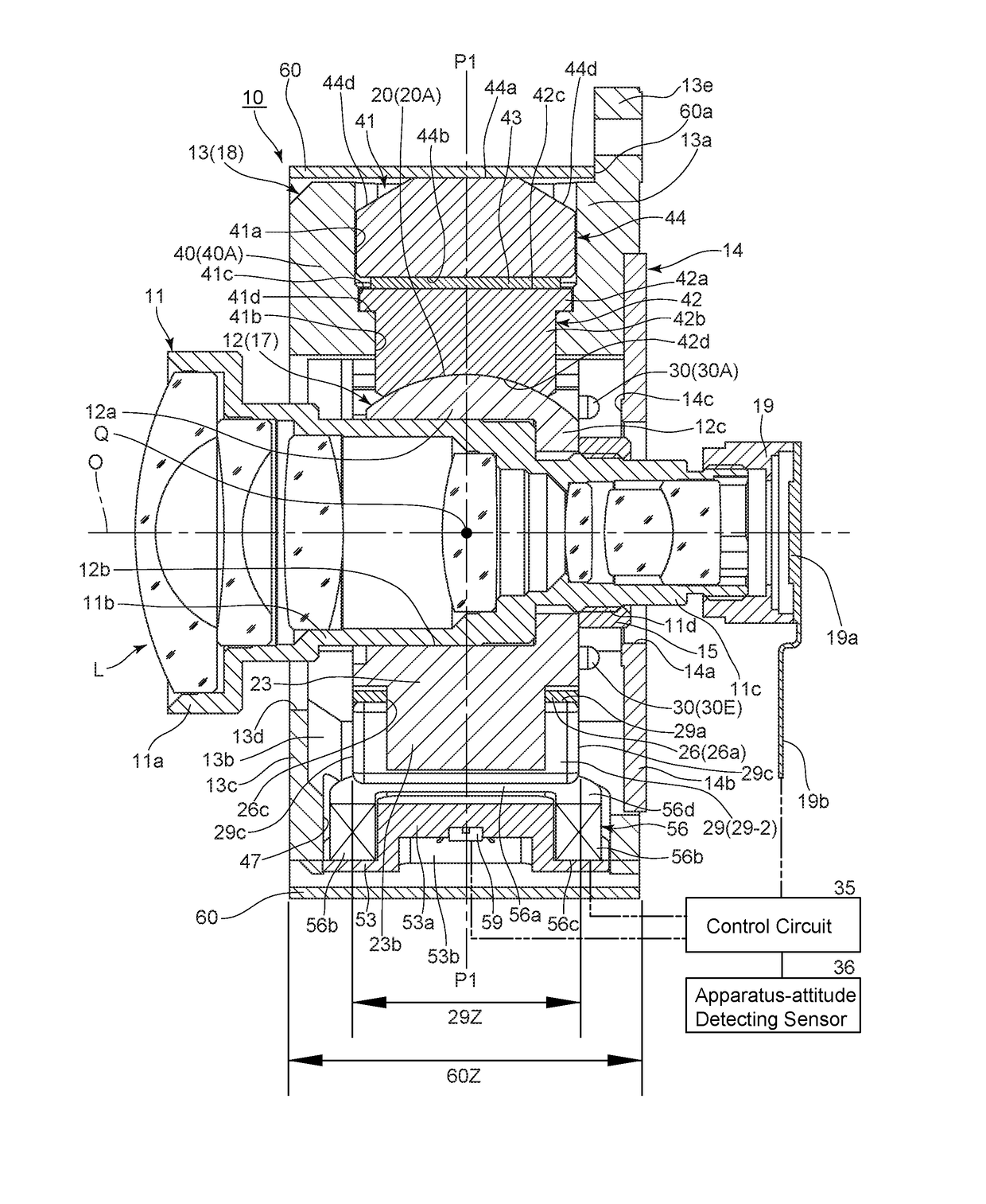
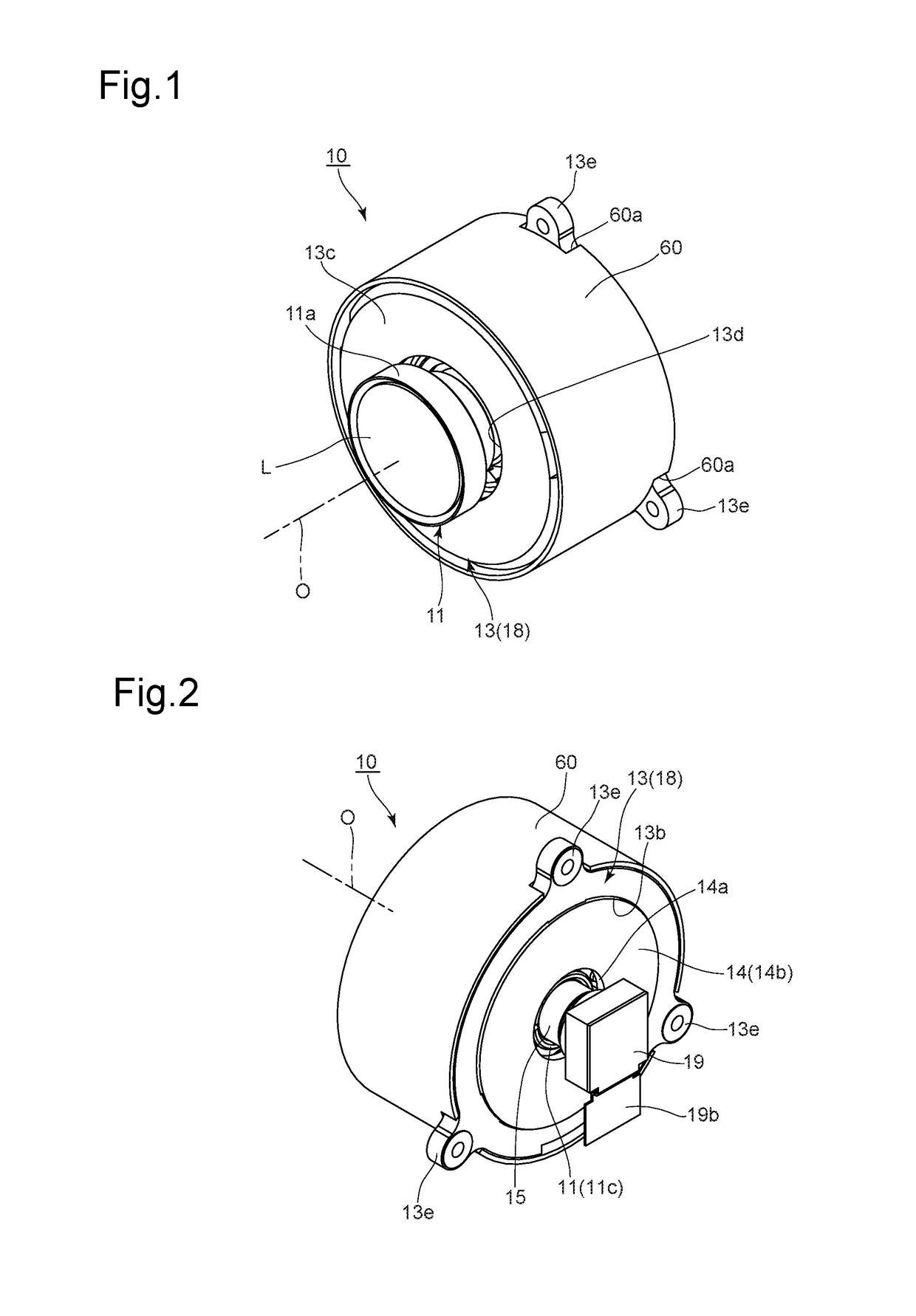
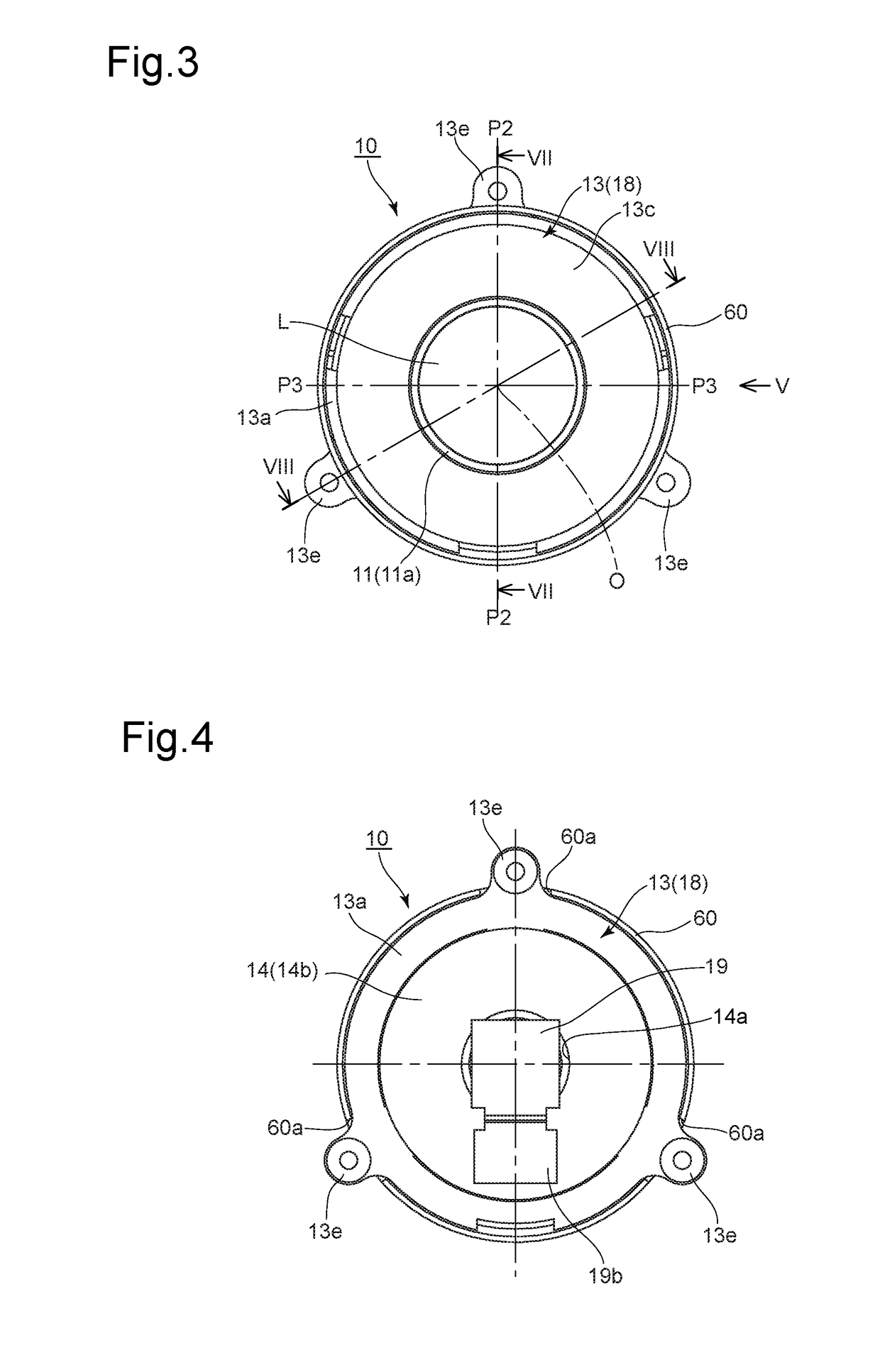
[0064]An embodiment (first embodiment) of an imaging apparatus 10 according to the present invention will be discussed below with reference to the attached drawings. The imaging apparatus 10 is provided with an imaging optical system L and an image sensor unit 19 as components of an imaging device for obtaining object images. A one-dot chain line O shown in the drawings designates the optical axis of an imaging optical system L provided in the imaging apparatus 10. In the following descriptions, the optical axis direction refers to a direction along, or parallel to, the optical axis O (a direction in which the optical axis O and an extension line thereof extend, or a direction in which a straight line parallel to the optical axis O extends), “front” refers to the object side, and “rear” refers to the image side with respect to the optical axis direction. In addition, a radial direction refers to a radial direction from the optical axis O (the direction in which a straight line norma...

second embodiment

[0152]The support member (supporter) 70 shown in FIG. 36, provided as an element of the imaging apparatus, is provided at the radially inner end (the lower end with respect to FIG. 36) with a support surface (supporter) 71. The support surface 71 is formed from a first flat surface portion 71a and a second flat surface portion 71b. The first flat surface portion 71a is a flat surface which is inclined radially outwards in the direction from front to rear in the optical axis direction (from left to right with respect to FIG. 36), while the second flat surface portion 71b is a flat surface which is inclined radially outwards in the direction from rear to front in the optical axis direction (from right to left with respect to FIG. 36). The radially outermost ends of the first flat surface portion 71a and the second surface portion 71b meet at the imaginary plane P1. The first flat surface portion 71a and the second flat surface portion 71b are substantially symmetrical in shape with re...

third embodiment

[0154]The support member (supporter) 72 shown in FIG. 37, provided as an element of the imaging apparatus, is provided at the radially inner end (the lower end with respect to FIG. 37) with a support surface (supporter) 73. The support surface 73 is formed from a first flat surface portion 73a, a second flat surface portion 73b and a third flat portion 73c. The first flat surface portion 73a is a flat surface which is inclined radially outwards in the direction from front to rear in the optical axis direction (from left to right with respect to FIG. 37), while the second flat surface portion 73b is a flat surface which is inclined radially outwards in the direction from rear to front in the optical axis direction (from right to left with respect to FIG. 37). The third flat portion 73c is a flat surface which is substantially parallel to the optical axis O and substantially orthogonal to the imaginary plane P1. The center of the third flat portion 73c in the optical axis direction li...


PUM


Abstract

An imaging apparatus includes a movable member which supports an imaging device, a supporter which supports the movable member in a manner to allow the movable member to spherically swing about a swing center on an optical axis of an optical system of the imaging device, and a driver which drives the movable member to perform an image-stabilizing operation. The supporter includes supported surfaces on the movable member at different circumferential positions, and support surfaces provided on the stationary member at different circumferential positions in the initial state, the supported surfaces being in slidable contact with the support surfaces. Each support surface defines a cylindrical surface having a central axis through the swing center in a direction orthogonal to the optical axis in the initial state, the cylinder having substantially the same radius as that of the spherical surface of an associated supported surface.

Description

BACKGROUND OF THE INVENTION[0001]1. Field of the Invention[0002]The present invention relates to an imaging apparatus equipped with an anti-shake (image shake correction / image stabilizing / shake reduction) system.[0003]2. Description of the Related Art[0004]Imaging apparatuses of recent years usually incorporate an anti-shake system for reduction of image shake caused by vibrations such as hand shake. Anti-shake systems detect vibrations applied to the imaging apparatus and / or variations in the orientation thereof, and shift an anti-shake optical element relative to the optical axis (i.e., move the anti-shake optical element in a plane orthogonal to the optical axis) or tilt the anti-shake optical element relative to the optical axis so as to cancel out the effect of the vibrations and the orientation variations. The anti-shake optical element comprises at least part (e.g., a lens group) of an imaging optical system or an image sensor.[0005]Due to increased diversification of the use...

Claims


Application Information

Patent Timeline
IPC IPC(8): H04N5/232
CPCH04N5/2328H04N23/57H04N23/51H04N23/54H04N23/685H04N23/687
Inventor MORINAGA, TAKAHIRO
Owner HOYA CORP
Why Eureka
Try Eureka