Constrained Prosthesis For The Knee Joint

a knee joint and prosthesis technology, applied in the field of constrained prosthesis, can solve the problem that the device may have to be removed, and achieve the effect of ensuring high mobility and stability of the joint itsel

Active Publication Date: 2017-10-05
TECRES SPA
View PDF2 Cites 12 Cited by
  • Summary
  • Abstract
  • Description
  • Claims
  • Application Information

AI Technical Summary

Benefits of technology

[0018]Still a further object of the present invention is to provide a constrained prosthesis that is pre-formed and, at the same time, adaptable to the actual conditions of the knee joint in which the same is to be implanted, also considering the amount of excised bone t...

Problems solved by technology

In the field of joint prosthesis implantology it is known that such devices may have to be removed for different...

Method used


Image

  • Constrained Prosthesis For The Knee Joint
  • Constrained Prosthesis For The Knee Joint
  • Constrained Prosthesis For The Knee Joint

Examples


Embodiment Construction

[0038]As known, articular surfaces in the knee joint are represented by femoral condyles and related tibial support bases.

[0039]The articular surface of the femur, consisting of the lower surface of the two condyles is smooth and ‘U’-shaped, it is articulated with the tibial plateau, that is the upper surface of the proximal epiphysis of the tibia.

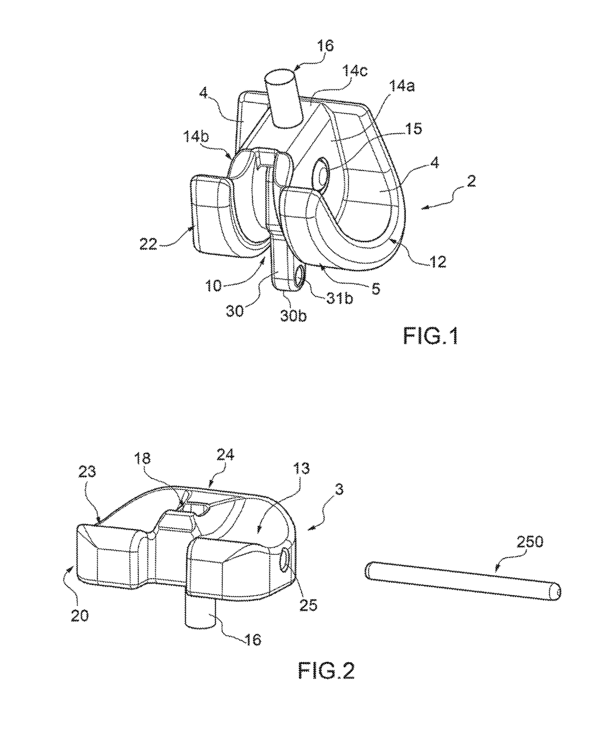
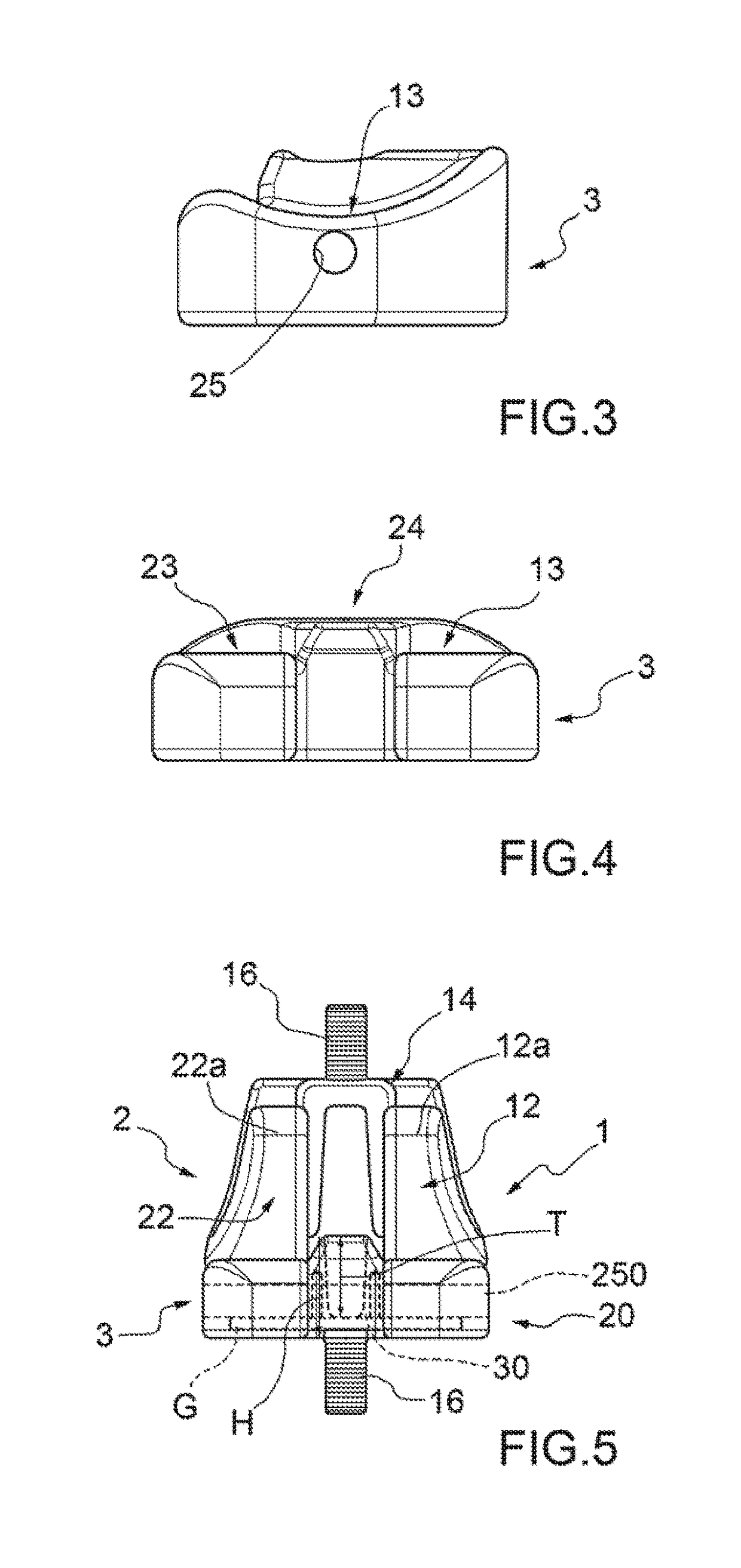
[0040]With reference to the enclosed figures, 1 generally indicates a constrained prosthesis for the knee joint.

[0041]The need to use a constrained prosthesis may derive from the fact that the ligaments of the patient to be treated may be particularly weak, or the resection of the bone may be too large, and therefore there is a need to insert a constrained prosthesis having an inherent stability.

[0042]The constrained prosthesis 1 according to the present invention may be used for example as a first implant or second or third implant, to be inserted following revision, if the already exposed reasons of joint weakness or lack of adequate bon...


PUM

PropertyMeasurementUnit
Lengthaaaaaaaaaa
Thicknessaaaaaaaaaa
Shapeaaaaaaaaaa

Abstract

Constrained prosthesis for the knee joint including a femoral component, a tibial component and an intermediate component, wherein the femoral component is suitable for being constrained to an end of the femoral bone in proximity to the knee joint, wherein the tibial component is suitable for being constrained to an end of the tibial bone in proximity to the knee joint, the femoral component being suitable for coming into contact and being articulated with the tibial component, wherein the intermediate component is placed in use between the femoral component and the tibial component and wherein the constrained prosthesis comprises a first hinge and a second hinge adapted to rotatably constrain the femoral component to the tibial component.

Description

TECHNICAL FIELD OF THE INVENTION[0001]The present invention relates to a constrained prosthesis which can be employed for knee prosthesis revision, for example following an infection. In this case, the constrained prosthesis according to the present invention is a revision prosthesis.STATE OF THE PRIOR ART[0002]Generally, the knee joint is formed by a pair of condyles placed in the distal portion of the femur. The lower surface of the condyles rests and slides / rolls on corresponding surfaces of the tibial plateau, shaped in a manner corresponding to the lower surface of the condyles themselves.[0003]The femur and the tibia are then connected by ligaments which confer stability to the joint.[0004]In the field of joint prosthesis implantology it is known that such devices may have to be removed for different reasons, in particular, due to local infections of the joint arising after the implantation of the prosthesis itself.[0005]In this case, after removing the first prosthesis, it is...

Claims


Application Information

Patent Timeline
IPC IPC(8): A61F2/38
CPCA61F2/3836A61F2220/0041A61F2/38A61F2/384A61F2/3859A61F2/389A61F2310/00011A61F2310/00592A61L27/04A61L27/306A61L27/34
Inventor SOFFIATTI, RENZOFACCIOLI, GIOVANNI
Owner TECRES SPA
Why Eureka
Try Eureka