Sealed hub and shaft fairing for rotary wing aircraft

a rotary wing aircraft and hub technology, applied in the field of rotary wing aircraft, can solve the problems of limiting aircraft speed, increasing the drag of the rotor system of the rotary wing aircraft, and relatively significant power penalty

Inactive Publication Date: 2017-10-05
SIKORSKY AIRCRAFT CORP
View PDF3 Cites 20 Cited by
  • Summary
  • Abstract
  • Description
  • Claims
  • Application Information

AI Technical Summary

Benefits of technology

[0006]In addition to one or more of the features described above or below, or as an alternative, further embodiments could include wherein the at least one of the upper hub fairing and the lower hub fairing includes a hub body and a plurality of hub shank regions, wherein portions of the hub body between the hub shank regions are locally thinner, while retaining a necessary thickness at the shank extension regions.
[0007]In addition to one or more of the features described above or below, or as an alternative, further embodiments could include wherein the upper rotor assembly and the lower rotor assembly include a plurality of rotor blades, and a vertical face seal is positioned about an outer mold line of at least one of the plurality of rotor blades.
[0008]In addition to one or more of the features described above or below, or as an alternative, further embodiments could include wherein a running surface of the vertical face seal is configured to seal a hub shank region of the hub fairing around a blade spanwise axis of the at least one of the plurality of rotors blade.
[0009]In addition to one or more of the features described above or below, or as an alternative, further embodiments could include wherein the vertical face seal is supported by the at least one of the upper hub fairing and the lower hub fairing.
[0010]In addition to one or more of the features described above or below, or as an alternative, further embodiments could include wherein the vertical face seal creates a constant running gap.
[0011]In addition to one or more of the features described above or below, or as an alternative, further embodiments could include wherein the shaft fairing is generally airfoil shaped.

Problems solved by technology

The rotor system drag increases for a rotary wing aircraft having a counter-rotating coaxial system primarily due to the additional rotor hub and the interconnecting main rotor shaft assembly between the upper and lower rotor systems.
For high speed rotary-wing aircrafts, the increased drag resulting from the counter-rotating coaxial rotor system may cause a relatively significant power penalty and / or limit aircraft speed.
The drag contributions may be approximately 40% for each of the rotor hubs, and 20% for the interconnecting shaft assembly; however, the effects are highly interactional, i.e., flow separation over one component may result in more significant flow separation and higher drag on another component.

Method used


Image

  • Sealed hub and shaft fairing for rotary wing aircraft
  • Sealed hub and shaft fairing for rotary wing aircraft
  • Sealed hub and shaft fairing for rotary wing aircraft

Examples


Embodiment Construction

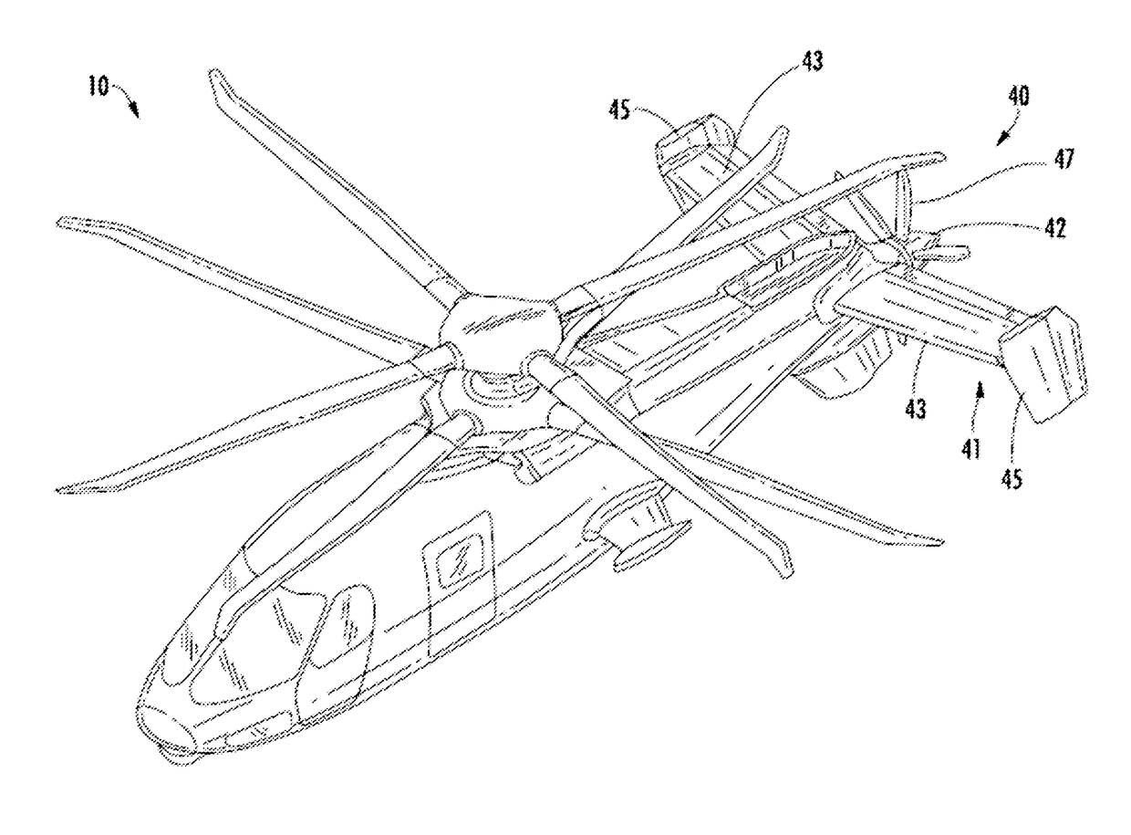
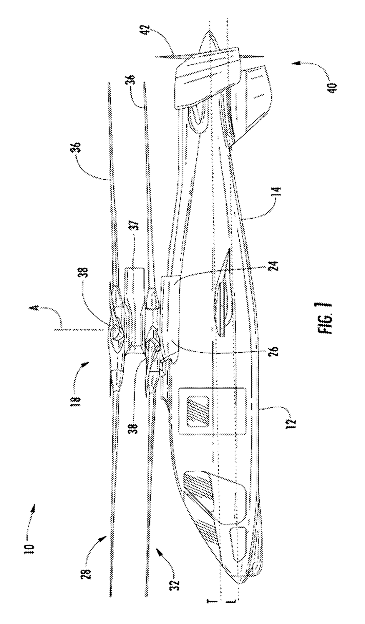
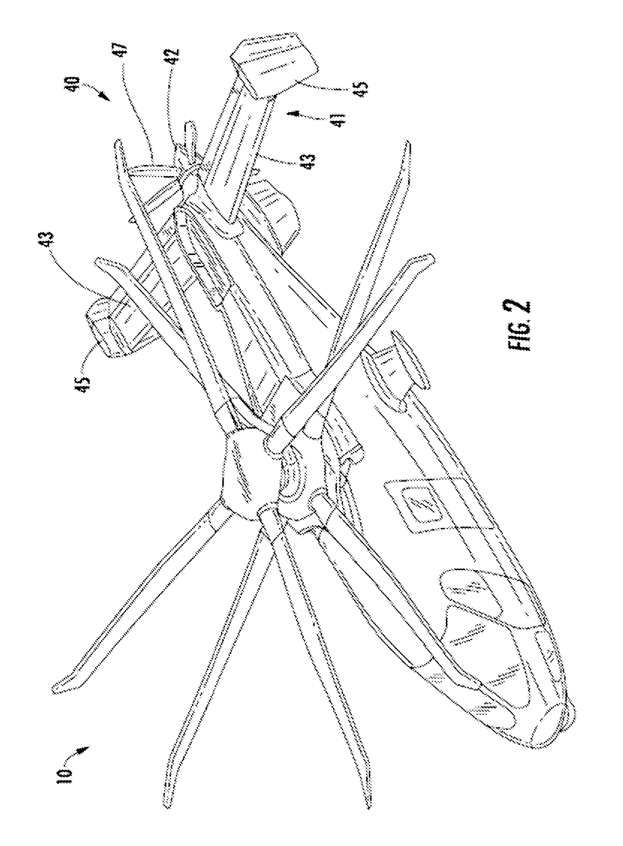
[0035]FIG. 1 depicts an exemplary embodiment of a rotary wing, vertical takeoff and land (VTOL) aircraft 10. The aircraft 10 includes an airframe 12 with an extending tail 14. A dual, counter rotating, coaxial main rotor assembly 18 is located at the airframe 12 and rotates about a main rotor axis, A. In an exemplary embodiment, the airframe 12 includes two seats for flight crew (e.g., pilot and co-pilot) and six seats for passengers. However an airframe 12 having another configuration is within the scope of the present disclosure. The main rotor assembly 18 is driven by a power source, for example, one or more engines 24 via a gearbox 26. The main rotor assembly 18 includes an upper rotor assembly 28 driven in a first direction (e.g., counter-clockwise) about the main rotor axis, A, and a lower rotor assembly 32 driven in a second direction (e.g., clockwise) about the main rotor axis, A, opposite to the first direction (i.e., counter rotating rotors). Each of the upper rotor assemb...


PUM


Abstract

An aircraft includes an airframe; an extending tail; a counter rotating, coaxial main rotor assembly including an upper rotor assembly and a lower rotor assembly; a translational thrust system positioned at the extending tail, the translational thrust system providing translational thrust to the airframe; an upper hub fairing positioned at the upper rotor assembly; a lower hub fairing positioned at the lower rotor assembly; and a shaft fairing disposed between the upper hub fairing and the lower hub fairing; wherein a geometry of at least one of the upper hub fairing and the lower hub fairing progressively blends from a circle to a series of curved elliptical surfaces in an inboard direction.

Description

CROSS-REFERENCE TO RELATED APPLICATIONS[0001]This application claims the benefit of U.S. provisional patent application Ser. No. 62 / 058,424, filed Oct. 1, 2014, and U.S. provisional patent application Ser. No. 62 / 058,153, filed Oct. 1, 2014, the entire contents of which are incorporated herein by reference.BACKGROUND[0002]The subject matter disclosed herein relates generally to rotary wing aircraft and, more particularly, to a dual rotor, rotary wing aircraft.[0003]Typically, aerodynamic drag associated with a rotor system of a rotary wing aircraft is a significant portion of the overall aircraft drag, commonly 25% to 30% for conventional single-rotor helicopters. The rotor system drag increases for a rotary wing aircraft having a counter-rotating coaxial system primarily due to the additional rotor hub and the interconnecting main rotor shaft assembly between the upper and lower rotor systems. For high speed rotary-wing aircrafts, the increased drag resulting from the counter-rotat...

Claims


Application Information

Patent Timeline
Patent Type & Authority Applications(United States)
IPC IPC(8): B64C27/10B64C7/00B64C27/473B64C27/82
CPCB64C27/10B64C27/82B64C2027/8236B64C27/473B64C7/00B64C27/14B64C2027/8272B64C2027/8281
Inventor EGOLF, THOMAS ALANBEATTY, ROBERT D.LAW, GARYBUTLER, CHRIS P.NUSSENBLATT, ERIC LUCIENREED, EDWARD
Owner SIKORSKY AIRCRAFT CORP
Why Eureka
Try Eureka