Electrolysis module

a technology of electrolysis module and electrode, which is applied in the direction of electrolysis components, water/sludge/sewage treatment, chemistry apparatus and processes, etc., can solve the problems of affecting the flow of fluid, increasing the cell voltage, and affecting the electrolysis efficiency, so as to improve the flow of electrical current, improve the electrolysis efficiency, and high electrical conductivity

Active Publication Date: 2017-10-05
TECHWIN
View PDF4 Cites 1 Cited by
  • Summary
  • Abstract
  • Description
  • Claims
  • Application Information

AI Technical Summary

Benefits of technology

[0031]According to the present invention, the inside surface of the inner electrode is plated with a metal having a high electrical conductivity to improve the flow of an electrical current. Therefore, the electrolysis module has improved electrolysis efficiency. In addition, since the electrolysis module is molded with a resin, safety of the electrolysis module can be guaranteed. That is, it is possible to prevent a risk of explosion attributable to a leakage of water and hydrogen gas and to prevent workers or operators from being electrically shocked.
[0032]In addition, since it is possible to reduce the number of parts to be assembled compared with conventional technologies, an assembling process is simplified. Furthermore, since the number of parts is reduced, the manufacturing cost is also reduced. Still further, since the electrolysis module requires a reduced installation space, it is possible to overcome a problem of space constraint.
[0033]In addition, the coupling of the assembled parts is not loosened by external vibrations. Since the molding treatment is performed with a transparent material, the state of the electrolysis module can be easily inspected or checked, maintenance of the electrolysis module can be conveniently performed, and a maintenance cost is reduced. In addition, the pipe-type electrolysis cell used in the electrolysis module of the present invention has a structure in which both the inside surface and the outside surface of the bipolar electrode can be used for electrolysis. Therefore, electrolysis efficiency is doubled compared with convention electrolysis cells having the same size. For this reason, it is possible to reduce the size and the manufacturing cost of the electrolysis module, which obviates a problem of space constraint when the electrolysis module is installed in a ship.
[0034]In addition, when a multi-stage electrolytic cell is constructed, even the surfaces of the electrodes that do not participate in an electrolytic reaction are plated with a metal having a high electrical conductivity. Therefore, current distribution in the electrode is uniformized, and thus uniformity and efficiency of electrolysis can be improved.

Problems solved by technology

Hardness materials such as Ca and Mg contained in sea water form scale on a cathode electrode through chemical reactions described below, during electrolysis, and the accumulated scale lowers electrolysis efficiency, resulting in an increase in cell voltage, impedes the flow of a fluid, and causes physical damage attributable to short-circuiting between electrodes in extreme cases.
However, in the case in which the flow rate of fluid, flowing along the fluid passage, is not constant but fluctuates, it is difficult to maintain uniform density of electromagnetic fields.
For this reason, it is difficult to effectively impede scale formation.
Therefore, it is not easy to substantially prevent scale formation, and thus it is necessary to mechanically remove generated scale.
However, in the case of the conventional pipe-type electrolysis cell, since only one surface of the electrode is involved in an electrolytic reaction, a large amount of material is likely to be wasted.
In addition, since the pipe-type electrolysis cell requires a large installation space, it is difficult to use the pipe-type electrolysis cell in small places.
In addition, since the number of parts of the pipe-type electrolysis cell is large and assembling of the parts is complicated, the manufacturing cost is increased.
In addition, in the case of the conventional pipe-type electrolysis cell, current distribution is non-uniform over the electrode.
Therefore, when the conventional pipe-type electrolysis cells are arranged in multiple stages, it is difficult to obtain uniform reaction, the life span of the electrode is shortened, and excessive heat is generated.

Method used


Image

  • Electrolysis module
  • Electrolysis module
  • Electrolysis module

Examples


Embodiment Construction

[0067]Hereinafter, a pipe-type electrolysis cell according to one embodiment of the invention and an electrolysis module including the pipe-type electrolysis cell will be described with reference to the accompanying drawings.

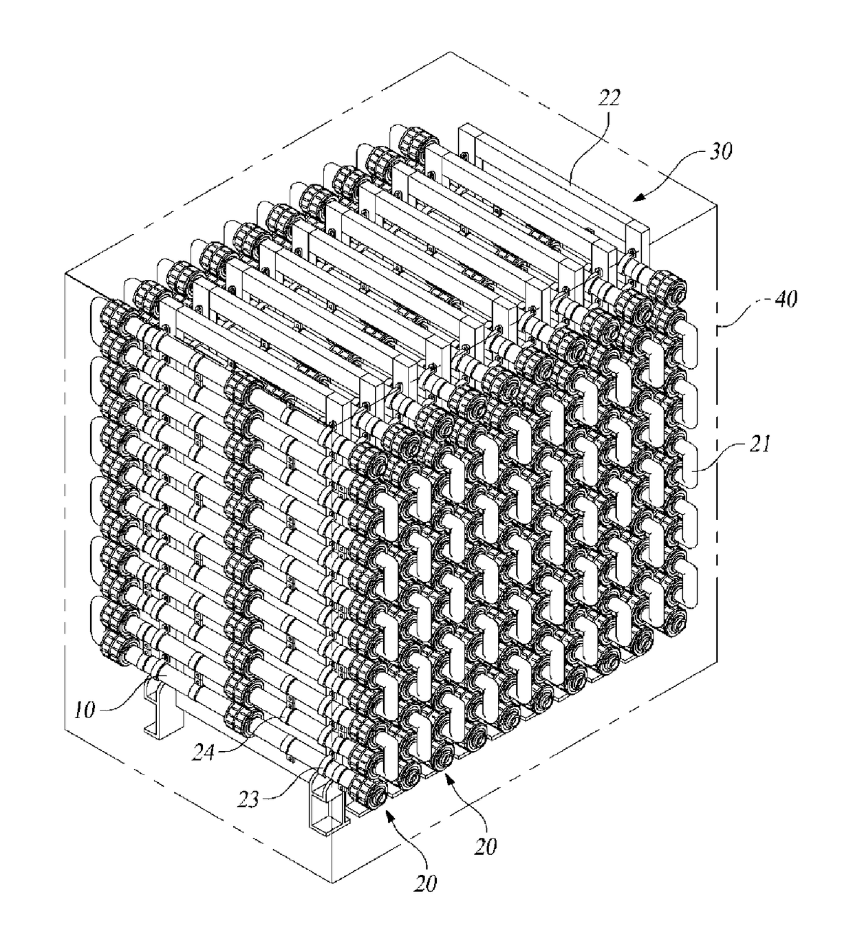
[0068]With reference to FIGS. 12 to 21, according to one embodiment, an electrolysis module 50 includes a electrolysis unit module 100, a molding case 200, a cell guide member 300, a power cable 400, and a resin layer 500.

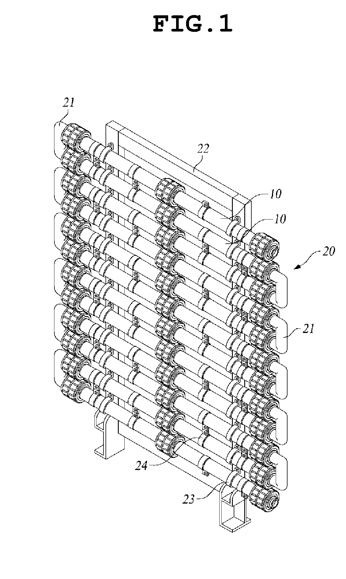
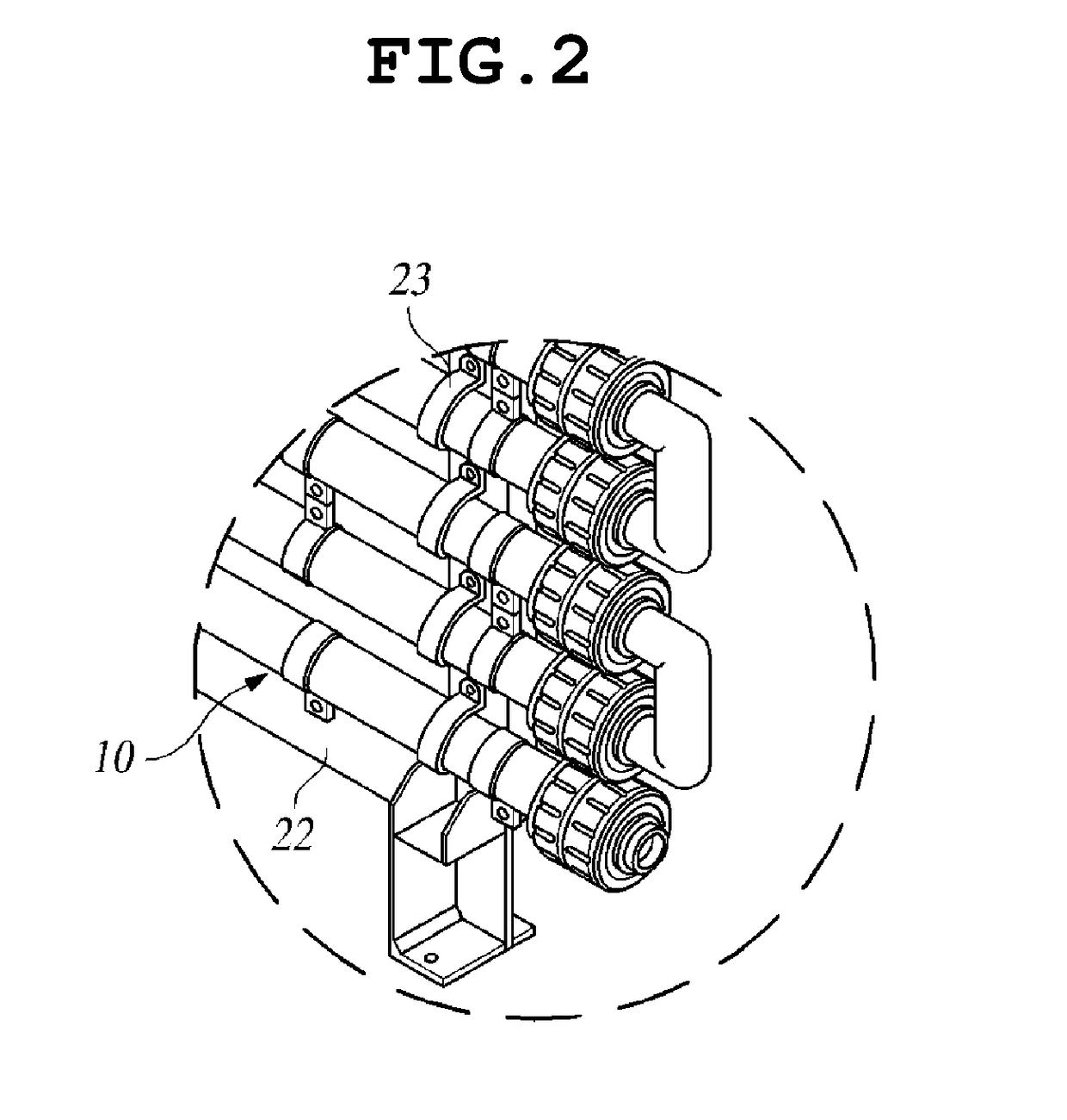
[0069]With reference to FIGS. 19 to 27, the electrolysis unit module 100 includes a pipe-type electrolysis cell 110, a connection pipe 120, and an inlet / outlet connection nipple 130.

[0070]With reference to FIGS. 19 to 27, the pipe-type electrolysis cell 110 includes a pair of terminal electrodes, a bipolar electrode, an insulation unit, and a spiral block 118.

[0071]Herein, the pair of terminal electrodes includes inner electrodes 115a and 115b, outer electrodes 114a and 114b, and connection plates 116 by which first ends of the inner electrodes...


PUM

PropertyMeasurementUnit
electrical conductivityaaaaaaaaaa
sizeaaaaaaaaaa
polarityaaaaaaaaaa

Abstract

Disclosed is an electrolysis module including: an electrolysis unit module including a plurality of pipe-type electrolysis cells connected in series with each other; a molding case surrounding the periphery of the electrolysis unit module to protect the electrolysis module; a cell guide member installed in the molding case to support the electrolysis unit module; a power cable having a first end connected to the electrolysis unit module and a second end extending to an outside through the molding case; and a resin layer formed by filling the inside of the molding case to cover the outer surface of the electrolysis unit module disposed in the molding case.

Description

CROSS-REFERENCE TO RELATED APPLICATIONS[0001]This application is a continuation application of International Application No. PCT / KR2015 / 011465 filed on Oct. 28, 2015, which claims priority to Korean Application No. 10-2014-0187429 filed on Dec. 23, 2014, which applications are incorporated herein by reference.TECHNICAL FIELD[0002]The present invention relates to an electrolysis module and, more particularly, to an electrolysis module constructed by connecting a plurality of unit modules in parallel with each other, each unit module including a plurality of pipe-type electrolysis cells connected in series with each other, each pipe-type electrolysis cell having a reduced size while providing advantages of a tube type electrolysis cell, whereby the pipe-type electrolysis cell can overcome a constraint of limited installation space and reduce manufacturing cost.BACKGROUND ART[0003]As a typical example of an electrolytic cell for electrolyzing sea water, fresh water, or the like, there ...

Claims


Application Information

Patent Timeline
Patent Type & Authority Applications(United States)
IPC IPC(8): C02F1/461C25B9/17
CPCC02F1/46109C02F2001/46171C02F2001/46128C25B1/04C25B1/265C25B9/70Y02E60/36C02F1/46104C02F2201/007C02F1/461
Inventor JUNG, BOONG IKKIM, JUNG SIKSHIN, HYUN SUKIM, MIN YONG
Owner TECHWIN
Why Eureka
Try Eureka