Aerial vehicle system

a vehicle system and vehicle technology, applied in the field of aircraft vehicles, can solve the problems of large power consumption limited operational endurance of unmanned aerial systems, and long operational time of payloads, and achieve the effect of optimizing the cost function

Active Publication Date: 2017-10-12
DRONA LLC
View PDF0 Cites 58 Cited by
  • Summary
  • Abstract
  • Description
  • Claims
  • Application Information

AI Technical Summary

Benefits of technology

[0011]According to one or more embodiments of the present disclosure, the processor in an aerial vehicle may include more than one processing units, e.g., a camera processing unit for processing data from each camera and a processing unit for integrating data from the camera processing units to calculate a navigation solution of the aerial vehicle. A camera processing unit may include at least one graphical processing unit.
[0012]According to one or more embodiments of the present disclosure, a tethered aerial vehicle system may include a ground station, an aerial vehicle including a frame and a plurality of spaced-apart rotors configured to spin about a substantially vertical axis during flight of the aerial vehicle, a stand-off joint coupled to the frame of the aerial vehicle, and a tether segment coupled between the ground station and the stand-off joint. The frame may define a planform that is substantially quadrilateral and surrounds the rotors to prevent contact of the rotors with the tether segment. The planform may include a slot and the stand-off joint may be pivotally movable through the slot. The stand-off joint may provide a substantially rigid or semi-rigid interconnect between the frame of the aerial vehicle and the tether segment. The stand-off joint may be coupled to the frame of the aerial vehicle by a universal joint, e.g., one formed by a pair of pivot joints with axes that are substantially orthogonal. Alternatively, the universal joint may be formed by a pair of eyebolts. The universal joint may include a tube formed of a composite material and a bushing mounted for rotational motion around the tube.
[0013]According to one or more embodiments of the present disclosur

Problems solved by technology

But the maneuverability of MUAS comes at a great cost in power consumption.
An unmanned aerial system (UAS), which may include multiple rotors, or other source of lift, are typically limited in operational endurance by on-b

Method used


Image

  • Aerial vehicle system
  • Aerial vehicle system
  • Aerial vehicle system

Examples


Embodiment Construction

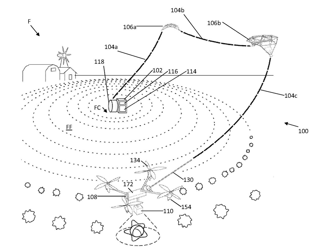
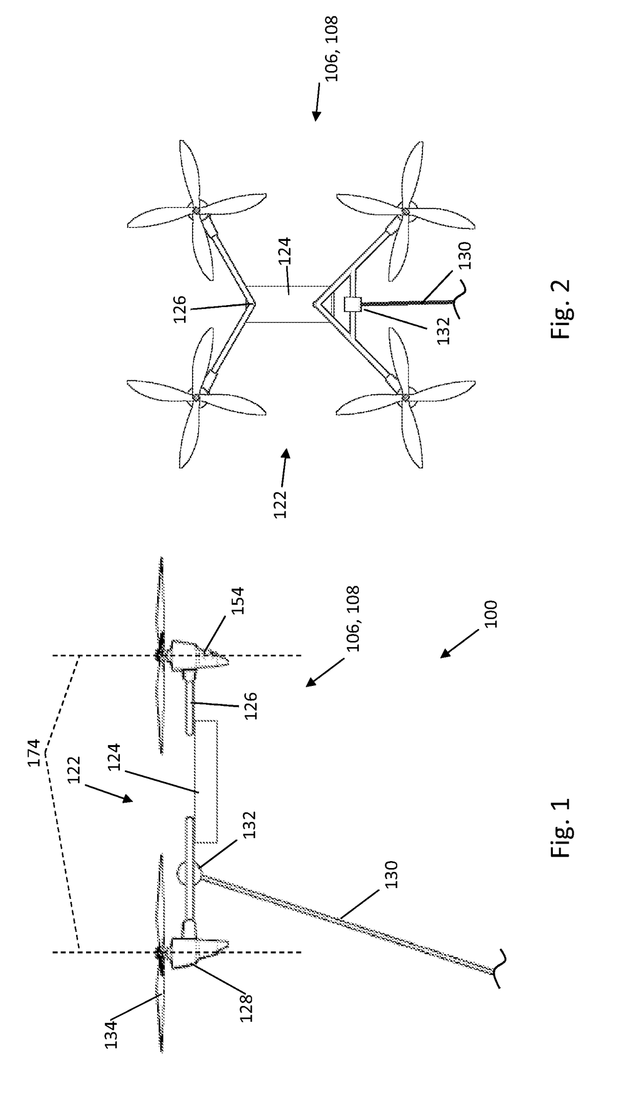
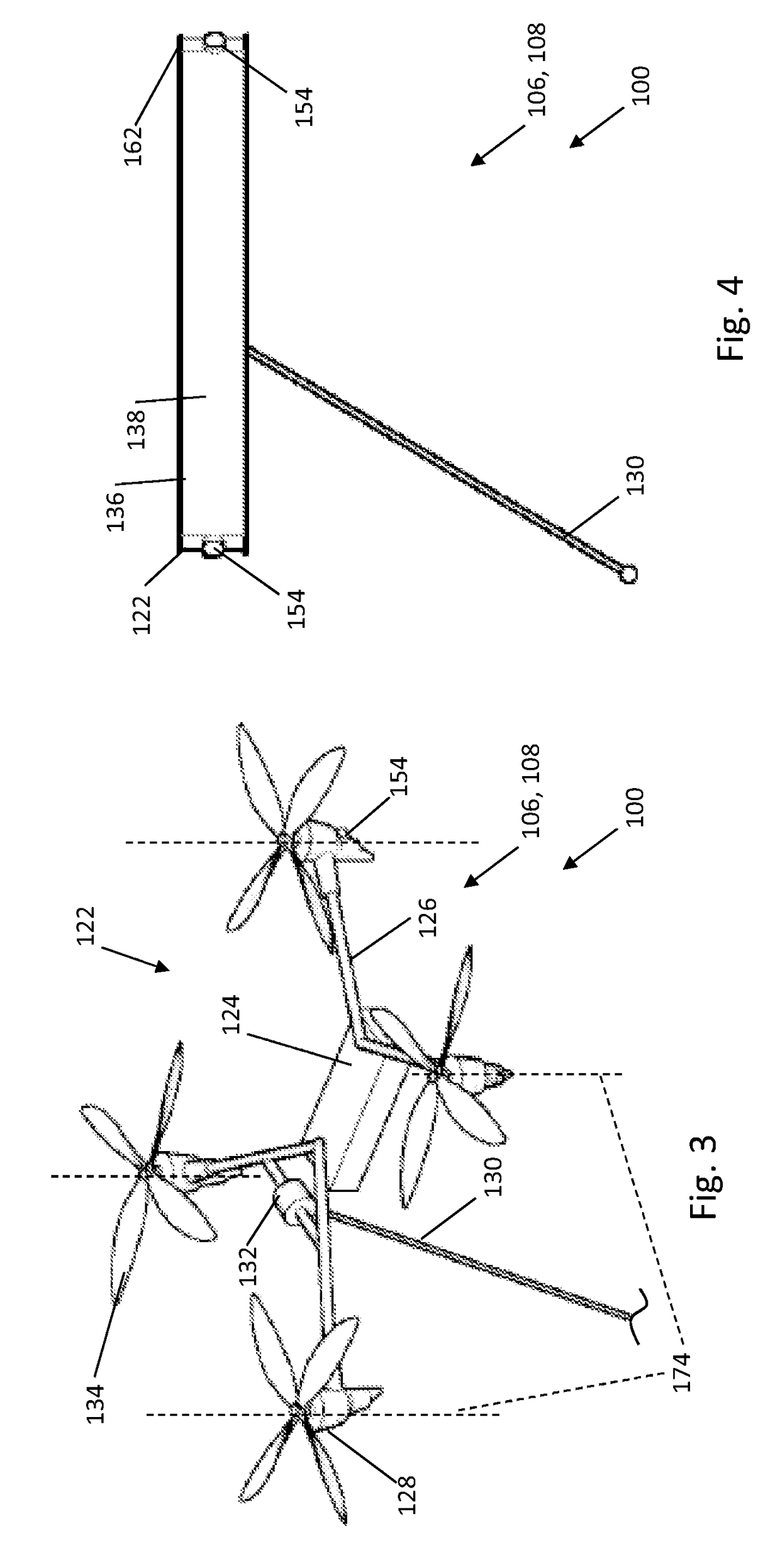
[0056]A system according to the present disclosure may include one or more aerial vehicles and may be tethered to a ground station or untethered. For example, the system may make use of one or more aerial vehicles, such as small, low-cost, electronically powered UAS units with onboard computational resources depicted in FIGS. 1-12. A system 100 may include a ground station 102, such as a base station, which may include a computer, a transmitter, and a power supply. Ground station 102 may remain at a fixed location during flight operations and typically is sized and configured to be transported to a location adjacent the flight operation. System 100 may include a tether 104 coupled to ground station 102 leading to one or more tether-carrying UAS(s) 106 and then to a primary UAS 108 with a data acquisition payload 110. Tether 104 may include a power line 112 (FIGS. 13 and 14) that may be maintained at a safe DC voltage and converted into a useful power source for the UAS by a DC-DC co...


PUM


Abstract

A system is provided for maneuvering a payload in an air space constrained by one or more obstacles, and may include first and second aerial vehicles coupled by a tether to a ground station. Sensor systems and processors in the ground station and aerial vehicles may track obstacles and the tether's and the vehicles' positions and attitude to maneuver the payload and the tether to carry out a mission. The sensor system may include airborne cameras providing data for a scene reconstruction process and simultaneous mapping of obstacles and localization of aerial vehicles relative to the obstacles. The aerial vehicles may include a frame formed substantially of a composite material for preventing contact of the rotors with the tether segments.

Description

BACKGROUND[0001]In recent years, advances have enabled aerial vehicles, such as multi-rotor unmanned aerial systems (MUAS) to navigate complex spaces under an operator's control. But the maneuverability of MUAS comes at a great cost in power consumption. An unmanned aerial system (UAS), which may include multiple rotors, or other source of lift, are typically limited in operational endurance by on-board energy storage.[0002]Numerous approaches to extending operational endurance focus on the energy storage, conversion, or power transmission. In embodiments of the present disclosure we describe a method of maneuvering a power and data line using an aerial vehicle system, which may include one or more accessory MUAS's. The method has advantages of economy, safety, and efficacy over previously described approaches. The power and data line may be provided by a tether and / or tether segments. The system may leverage a wide-bandwidth optical communication along the tether and / or tether segm...

Claims


Application Information

Patent Timeline
IPC IPC(8): B64C39/02G01S17/02B64D47/08G01S15/02G01S19/13G01C21/16G05D1/00G01S13/02G01S13/933G01S17/933
CPCB64C39/022G05D1/0011G01S17/02G01S13/02G01S15/02B64C2201/141G01C21/16B64C39/024B64D47/08B64C2201/027B64C2201/06G01S19/13G01C21/005G01S17/933G05D1/0866G05D1/104G08G5/0013G08G5/0039G08G5/0043G08G5/0069G08G5/0086G08G5/045G01S19/15G01S5/16G01S5/163G01S13/933B64U50/34B64U10/13B64U2101/60B64U2101/30B64U2201/10B64U2201/102G01C21/1652G01C21/1656G01C21/1654
Inventor ALEGRIA, LOREN
Owner DRONA LLC
Why Eureka
Try Eureka