Self propelling subterranean vehicle

a self-propelled, subterranean technology, applied in the direction of surveying, directional drilling, borehole/well accessories, etc., can solve the problems of energy loss, lack of attitude constancy, ineffectiveness, etc., and achieve the effect of efficient and controllabl

Inactive Publication Date: 2017-10-12
HAYIK ISAAK
View PDF4 Cites 14 Cited by
  • Summary
  • Abstract
  • Description
  • Claims
  • Application Information

AI Technical Summary

Benefits of technology

[0013]It is the objective of the present invention to provide a self-propelling s

Problems solved by technology

Certain configurations of a vehicle to meet the needs have been suggested, but are deemed inadvantageous or ineffective.
A major disadvantage or this configurati

Method used


Image

  • Self propelling subterranean vehicle
  • Self propelling subterranean vehicle
  • Self propelling subterranean vehicle

Examples


Embodiment Construction

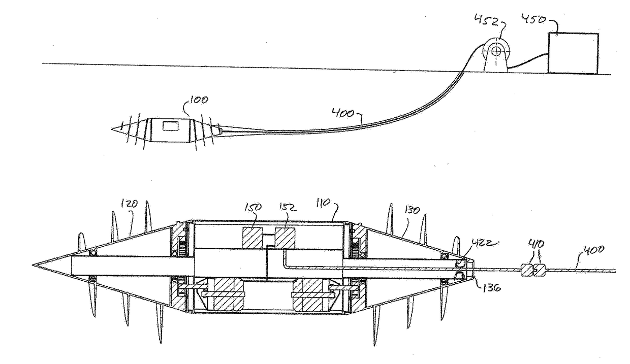
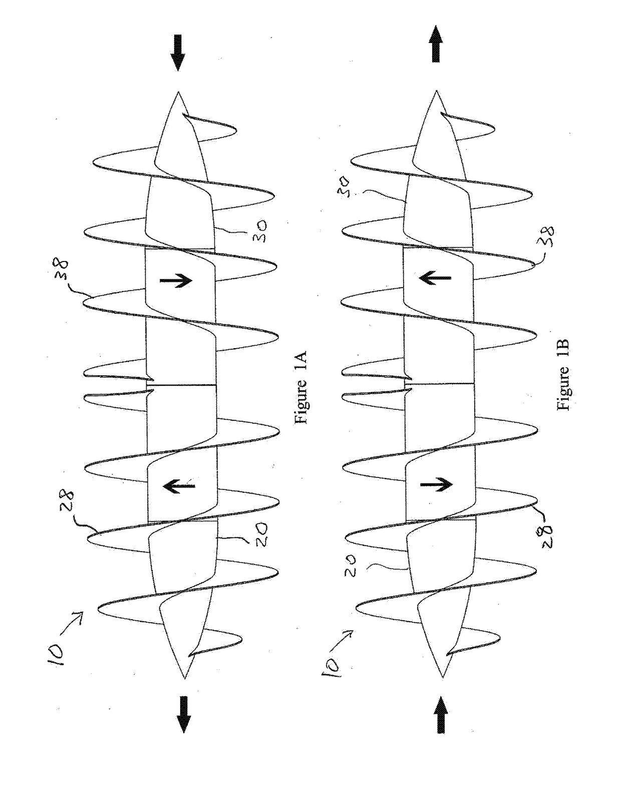
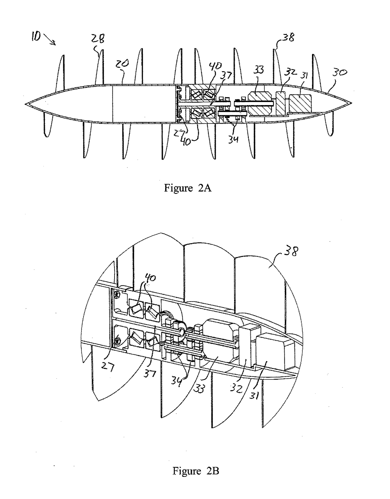
[0060]Turning first to FIGS. 1 and 2, there is shown schematically—in an overall view and in a longitudinal section view, respectively—an embodiment of a first configuration of a self propelling vehicle (STV) according to the present invention. It is seen to comprise basically a hollow oblong cylindrical capsule 10, generally similar in overall shape to a torpedo, that is divided lengthwise into two essentially similar members 20 and 30, mutually joined through a bearing or a set of bearings 40 so that the two members are mutually rotatable, the rotation being essentially about the central longitudinal axis of the capsule. The two rotating members will be referred to in the sequel also as rotors. The bearings 40 may be seen in greater detail in the enlarged view of FIG. 2B. The member on the left, which may be thought of as the fore member 20, serves generally as a container for payload, while the member on the right, which may be thought of as the aft member 30, serves generally as...


PUM


Abstract

A self propelling vehicle capable of propagating through a solid medium, comprising two or more rotors, arranged in tandem, and means for rotating the rotors, each rotor being formed as a hollow rotational body with an external helicoidal flighting, configured to engage surrounding solid medium, wherein the flightings of any pair of adjacent rotors follow helicoids of mutually opposite senses and the means for rotating are operative to rotate the adjacent rotors in mutually opposite senses.

Description

TECHNICAL FIELD[0001]The field of the invention is subterranean vehicles, i.e. vehicles that can travel underground and burrow through soil or other media.BACKGROUND ART[0002]There is a widespread and increasing need for inexpensive means to access underground sites, or to reach remote sites by traveling underground, and to perform any of a variety of operations at, or enroute to, such a site. The need may arise, for example, in civilian and military applications such as:[0003]Rescue missions,[0004]Geological, hydrological or archaeological research and exploration,[0005]Mining and underground construction,[0006]Laying pipes and cables[0007]Seismic monitoring,[0008]Intelligence operations,[0009]Destroying underground spaces and structures,[0010]There is likewise a need for means to access sites within other solid media, such as industrial waste, trash heaps or even organic and biological matter. In the sequel, all references to ground and soil should be understood to possibly also m...

Claims


Application Information

Patent Timeline
IPC IPC(8): E21B7/26E21B7/06E21B10/44E21B4/00
CPCE21B7/26E21B4/00E21B47/09E21B10/44E21B49/02E21B7/06B62D57/036E21B4/04E21B7/203E21B7/267
Inventor HAYIK, ISAAK
Owner HAYIK ISAAK
Why Eureka
Try Eureka