
Fusion neutron-source power system

a power system and neutron source technology, applied in nuclear reactors, nuclear engineering problems, greenhouse gas reduction, etc., can solve the problems of high cost, large current fusion reactors, and many technological challenges in laboratory fusion, so as to achieve more neutrons, save energy, and save resources

Inactive Publication Date: 2017-10-12
MAKHLOUF SAADE YOUSSEF
View PDF2 Cites 6 Cited by
  • Summary
  • Abstract
  • Description
  • Claims
  • Application Information

AI Technical Summary

Benefits of technology

The invention is a compact fusion reactor that offers a safe and controlled On-Off nuclear power. It is designed to generate plasma of a longer life with more neutrons, which can be operated at optimal efficiency, leading to economic electricity production. The reactor structure is protected from neutron damage with a continuously changing protective film, and it produces a high-density hot stable plasma without external magnets. The mass implementation of this reactor can respond to the urgent needs for power anywhere on the globe because no critical, difficult, or costly developments are required.

Problems solved by technology

Sustaining fusion under laboratory conditions presents many technological challenges.
However, fast neutrons of 14 Mev irradiate the vacuum vessel and deteriorate it.
Current fusion reactors are very large, cost billions of dollars and face numerous technological difficulties such as limited magnetic field strength, energy loss from plasma instabilities, heat losses and particle drift across the magnetic fields among other difficulties, most of these technical challenges come from the design of the reactors.
There are some really difficult engineering problems with current designs of fusion reactors that have not been overcome despite forty years of concerted effort and well over $20 billion spent on the research.
The issues include the potentially prohibitive constructions costs, and the difficulties of repairing and maintaining the reaction vessel.

Method used


Image

  • Fusion neutron-source power system
  • Fusion neutron-source power system
  • Fusion neutron-source power system

Examples


Embodiment Construction

[0032]The following description is not intended to limit the scope of the invention in any way as they are exemplary in nature, serving to describe the best mode of the invention known the inventors as of the filing date hereof. Consequently, changes may be made in the arrangement and / or function of any of the elements described in the exemplary embodiments disclosed herein without departing from the spirit and scope of the invention.

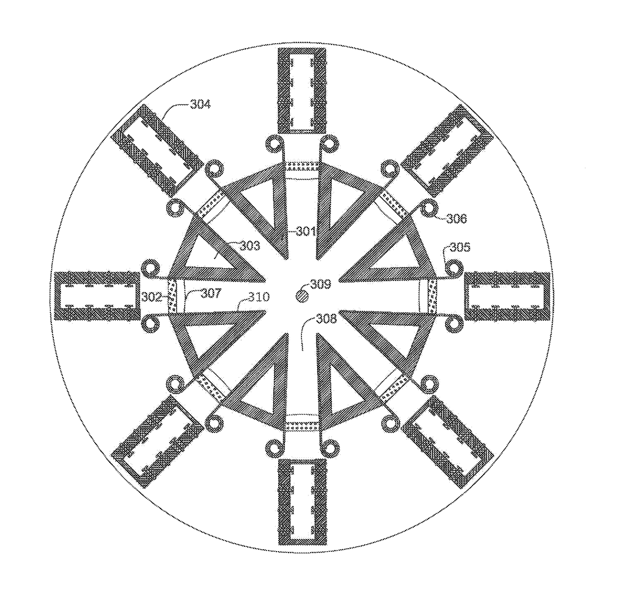
[0033]The fusion reactor of this invention consists of a plurality of triangular elongated electrodes aligned in a cylindrical shape to form an axially symmetric containment geometry wherein said electrodes are separated by means of a wall of pure Quartz (SiO2). The Triangular electrodes, made out of very high electro conductive, high strength, heat resistant, radiation resistant and neutron moderating material such as thorium carbide, uranium carbide or silicon carbide or the like are preferably made by ceramic powder metallurgy process. The electrodes...


PUM

PropertyMeasurementUnit
electro conductiveaaaaaaaaaa
strengthaaaaaaaaaa
heat resistantaaaaaaaaaa

Abstract

The fusion reactor of the invention comprises a plurality of elongated triangular electrodes aligned in a cylindrical shape to form an axially symmetric containment geometry. The electrodes are separated by means of electrical insulator preferably pure swept Quartz (SiO2). The Triangular electrodes, are made out of very high electro conductive, high strength, heat resistant, radiation resistant and neutrons moderating material such as thorium carbide, uranium carbide or silicon carbide or the like which is preferably made by ceramic powder metallurgy process. Each electrode includes a cooling structure or flow channel formed in the internal structure allowing for a cooling fluid for extracting heat caused by plasma and nuclear reactions. The acceleration channels electrodes of the fusion reactor are of triangular shape and are protected with a continuously changing protective film or layer of high electro-conductive fissile or fertile material such as thorium carbide or uranium carbide. Lithium may be added for the reactor to breed its own Tritium.

Description

CROSS REFERENCE TO RELATED APPLICATIONS[0001]This application claims the benefit of U.S. Provisional Application No. 62 / 118,470, filed Feb. 20, 2015, a copy of which is incorporated herein by reference and relied upon.COPYRIGHT & LEGAL NOTICE[0002]A portion of the disclosure of this patent document contains material which is subject to copyright protection. The Applicant has no objection to the facsimile reproduction by anyone of the patent document or the patent disclosure as it appears in the Patent and Trademark Office patent file or records, but otherwise reserves all copyright rights whatsoever. Further, no references to third party patents or articles made herein is to be construed as an admission that the present invention is not entitled to antedate such material by virtue of prior invention.BACKGROUND OF THE INVENTION[0003]This invention relates to the field of thermonuclear reactors for producing safe and controlled nuclear power. More specifically this invention is relate...

Claims


Application Information

Patent Timeline
Patent Type & Authority Applications(United States)
IPC IPC(8): G21B1/05G21B1/11
CPCG21B1/05G21B1/11G21Y2004/30G21Y2002/20G21Y2002/201G21Y2002/104G21B3/006H05H1/04H05H1/48Y02E30/10
Inventor MAKHLOUF, SAADE YOUSSEF
Owner MAKHLOUF SAADE YOUSSEF
Learn More