High frequency discharge ignition apparatus

a high frequency energy and ignition apparatus technology, applied in the direction of electrical apparatus casings/cabinets/drawers, spark gap circuits, casings/cabinets/drawers details, etc., can solve the problems of reducing combustion performance, reducing startability, and difficult to produce spark discharge for starting combustion, so as to reduce the length of the loop in which high frequency energy is conducted and reduce noise

Inactive Publication Date: 2017-10-12
MITSUBISHI ELECTRIC CORP
View PDF4 Cites 6 Cited by
  • Summary
  • Abstract
  • Description
  • Claims
  • Application Information

AI Technical Summary

Benefits of technology

[0010]According to the high frequency discharge ignition apparatus of the present invention, the length of the loop in which high frequency energy is conducted is reduced, whereby noise can be reduced.

Problems solved by technology

However, it is known that in a high-supercharge state, the pressure in an engine combustion chamber becomes very high even when no combustion occurs, which makes it difficult to produce a spark discharge for starting combustion.
However, if the gap of the ignition plug is narrowed, the influence of the extinguishing action by electrode portions becomes large in turn, which causes problems such as reduced startability and reduced combustion performance.

Method used


Image

  • High frequency discharge ignition apparatus
  • High frequency discharge ignition apparatus
  • High frequency discharge ignition apparatus

Examples


embodiment 1

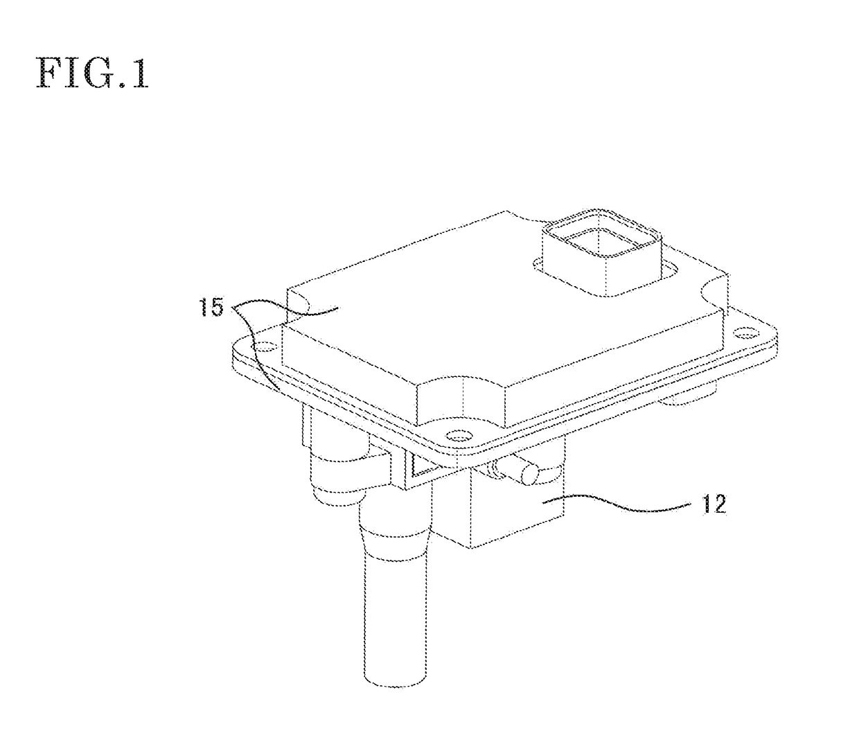
[0053]FIG. 1 is a perspective view of a high frequency discharge ignition apparatus having been assembled, in embodiment 1 of the present invention.

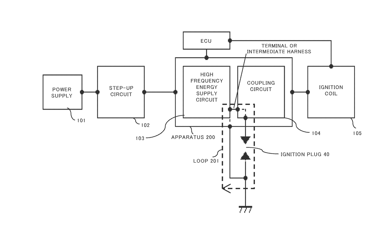
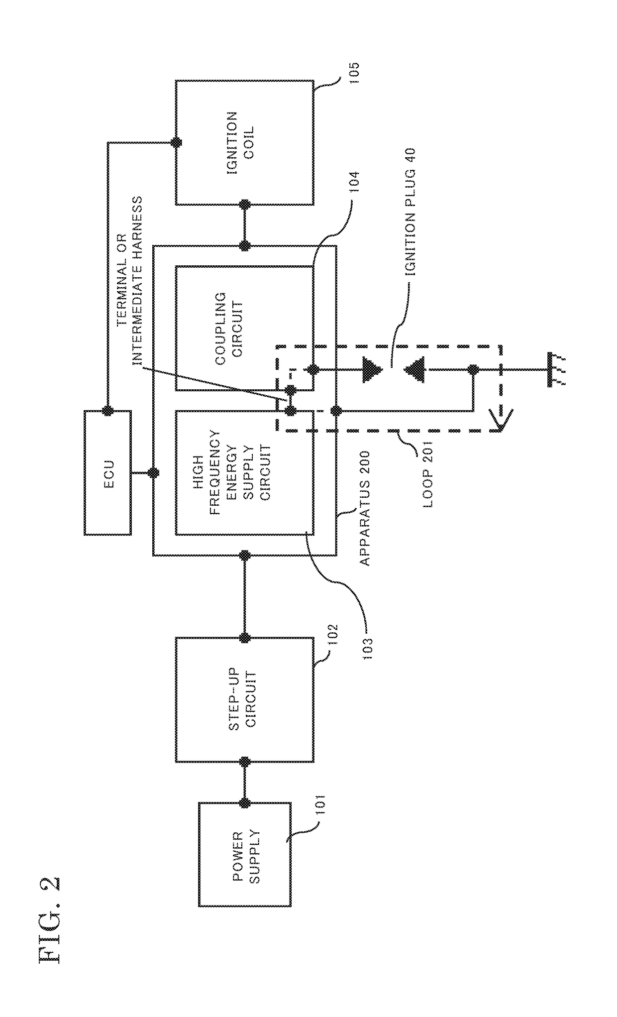
[0054]FIG. 2 is a block diagram of a circuit configuration of the high frequency discharge ignition apparatus in embodiment 1 of the present invention. Compared with a conventional example shown in FIG. 31, no high-voltage cable is present, and a loop 201 in which high frequency energy is conducted is short.

[0055]FIG. 3 is an exploded perspective view showing an example of an internal structure of the high frequency discharge ignition apparatus in embodiment 1 of the present invention. The high frequency discharge ignition apparatus in the present embodiment 1 includes the following components: a cover 1; a connector 2; an electronic circuit board 3; electronic components 4 provided on the electronic circuit board 3; a base 5; a packing 6; a terminal 7; an electronic component 8; terminal members 9, 10, and 11; a first housing 12; bolts ...

embodiment 2

[0099]In embodiment 1 above, the packing 6 is inserted or an adhesive is used in the groove portion 24 in a resin material multiple molded portion of the terminal 7, whereby waterproofing with the base 5 is realized. However, instead of the resin material multiple molded portion of the terminal 7, a lid 45 may be used to ensure waterproofing with the base 5. FIG. 24 shows a component configuration in the case where the lid 45 is used.

[0100]The lid 45 includes: on the outer face thereof, a groove portion 46 and a fit portion 47 for fitting the lid 45 the terminal 7 to each other; and on the rear face of the lid 45, a protrusion 48 having a height that allows the protrusion 48 to be immersed in the cast resin 32 (see FIG. 25). The positional relationship between the terminal 7 and the lid 45 is determined according to the size of the fit portion 47.

[0101]As in embodiment 1 above, the first housing 12 and the lid 45 may be fixed to each other by means of the cast resin 32, after the co...

embodiment 3

[0104]In embodiment 1 above, as shown in FIG. 27A, the terminal 7 is inserted in the through hole 21 in the electronic circuit board 3, and is electrically connected to a circuit (not shown) such as an input / output portion of the electronic circuit board 3. However, without using the electronic circuit board 3, the terminal 7 and an electronic component may be directly connected to each other.

[0105]For example, as shown in FIG. 27B, the circuit such as an input / output portion of embodiment 1 may be replaced with a circuit composed of an electronic component 49 and a plurality of other components, and the terminal 7 and the electronic component 49 may be electrically connected to each other.

[0106]Thus, the structure according to embodiment 3 makes it possible to provide electric connection even for a circuit that does not use a circuit board.


PUM


Abstract

In order to transmit high frequency energy to a coupling circuit, if the high frequency energy is transmitted via a harness provided with a high-voltage cable, the loop in which the high frequency energy is conducted is long, and thus, noise occurring from the loop is increased. Thus, shielding is needed to be provided to the entire apparatus. The present invention has a structure in which: a high frequency energy supply circuit and a coupling circuit are connected by a connection member; and a housing having therein the high frequency energy supply circuit is integrated with a housing having therein the coupling circuit. Accordingly, the entire apparatus can be downsized and noise occurring from the loop can be reduced.

Description

BACKGROUND OF THE INVENTIONField of the Invention[0001]The present invention relates to a structure of a high frequency discharge ignition apparatus that is mainly used in an internal combustion engine.Description of the Related Art[0002]In recent years, issues such as environment preservation and fuel depletion have been raised, and measures for these issues should be urgently taken also in the automobile industry. As example of such measures, there is a method for improving fuel consumption through engine downsizing by use of a supercharger.[0003]However, it is known that in a high-supercharge state, the pressure in an engine combustion chamber becomes very high even when no combustion occurs, which makes it difficult to produce a spark discharge for starting combustion. In order to solve this problem, it is necessary to narrow the gap interval in an ignition plug to increase the withstand voltage. However, if the gap of the ignition plug is narrowed, the influence of the extingui...

Claims


Application Information

Patent Timeline
Patent Type & Authority Applications(United States)
IPC IPC(8): H01T15/00H05K5/04H05K5/02
CPCH01T15/00H05K5/04H05K5/0247F02P3/01F02P3/02F02P3/0407F02P9/007H01F38/12
Inventor SHIMIZU, YASUYUKITANAKA, TAKAAKINARUSE, YUSUKE
Owner MITSUBISHI ELECTRIC CORP
Why Eureka
Try Eureka