Built-in multifunctional dyeing device with gas-liquid spray dyeing system

A dyeing equipment and built-in technology, applied in the field of dyeing machinery, can solve problems such as affecting the dyeing effect of fabrics, reducing the service life of driving motors, reducing fabric stacking space, etc., so as to reduce the risk of dyeing defects, reduce space occupation, and reduce circulation. effect of length

Pending Publication Date: 2018-05-08
郑州科信印染设备有限公司
View PDF8 Cites 3 Cited by
  • Summary
  • Abstract
  • Description
  • Claims
  • Application Information

AI Technical Summary

Problems solved by technology

[0005] 1) The problem of fabric cycle power, the friction between the cloth lifting wheel of the cloth lifting mechanism and the fabric in the fabric cycle lifts the fabric to the gas-liquid spraying system for spraying, during the process of lifting the fabric, the cloth lifts The wheel is easy to scratch the fabric, resulting in damage to the fluff of the fabric. In actual production, try to reduce the effect of the cloth lifting wheel. The ideal state is not to use the cloth lifting wheel;
[0006] 2) The problem of the dyeing nozzle setting. The fabric to be dyed in the cylinder is first blown by high-speed airflow and then sprayed with dye solution for coloring, or the dye solution is sprayed first and then blown by high-speed airflow. This will easily cause the dye solution to be uneven and effective. Contact, resulting in uneven dyeing of the fabric, seriously affecting the dyeing effect of the fabric, making the finished product rate of the fabric low;
[0007] 3) The fan and the drive motor of the fan are coaxially arranged at one end of the cylinder body, which still takes up a large space in the horizontal direction, which causes waste of space, and the drive motor of the fan drives the fan coaxially. During the long-term operation of the drive motor , due to the need for overfrequency and high-speed operation, the normal fan speed is 4000 rpm, which requires high technical parameters such as motor bearings and motor insulation; at the same time, due to the high temperature transmission of the fan to the output shaft, it will cause serious damage to the output shaft and bearing of the drive motor. damage, thereby reducing the service life of the drive motor and increasing the maintenance cost of the equipment;
[0008] 4) The electrical control cabinet adopts the form of single-cabinet control, that is, the control cabinet and the power distribution cabinet are combined, which results in the size of the cabinet being too large and occupying a large space
Moreover, the control module and the power distribution module are arranged in the same cabinet, which reduces the safety of the power distribution cabinet as a whole;
[0009] 5) The fabric after spray dyeing is stacked horizontally and vertically by two sets of left and right devices. The two sets of left and right devices occupy a large space in the cylinder, resulting in reduced fabric stacking space, and the requirements for the cooperation degree of the two sets of left and right devices are relatively high. High, once the two sets of left and right devices are not well matched, it is easy to cause the fabric to be scattered and stacked, which will affect the work of the finished fabric

Method used


Image

  • Built-in multifunctional dyeing device with gas-liquid spray dyeing system
  • Built-in multifunctional dyeing device with gas-liquid spray dyeing system
  • Built-in multifunctional dyeing device with gas-liquid spray dyeing system

Examples


Embodiment Construction

[0052] The following will clearly and completely describe the technical solutions in the embodiments of the present invention with reference to the accompanying drawings in the embodiments of the present invention. Obviously, the described embodiments are only some, not all, embodiments of the present invention. Based on the embodiments of the present invention, all other embodiments obtained by persons of ordinary skill in the art without making creative efforts belong to the protection scope of the present invention.

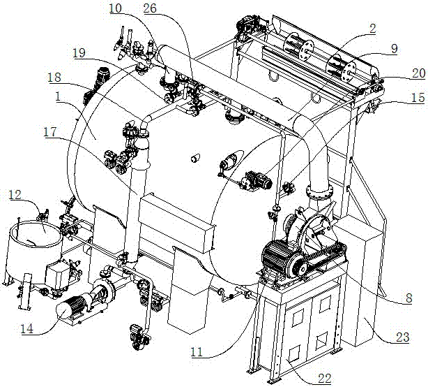
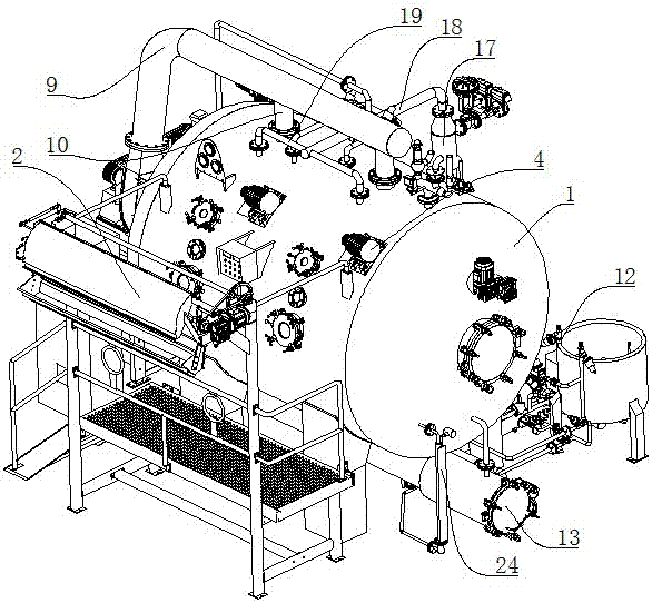
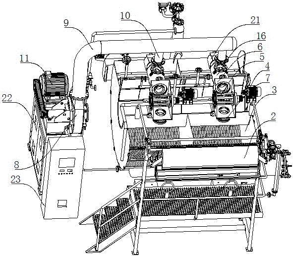
[0053] Such as Figure 1-8 And shown in 14-15, a kind of air-liquid spray dyeing system built-in multifunctional dyeing equipment, including cylinder body 1, cloth inlet and outlet device 2, gas-liquid spray dyeing system and electrical control device; the inner wall of the cylinder body 1 is provided with Cloth storage tank 3, said cloth storage tank 3 is composed of several polytetrafluoroethylene tubes with semicircular arc structure closely arranged along ...


PUM


Abstract

The invention relates to a built-in multifunctional dyeing device with a gas-liquid spray dyeing system. The built-in multifunctional dyeing device comprises a cylinder, a cloth feeding and discharging device, the gas-liquid spray dyeing system and an electric control device. The cylinder serves as a device body, and a cloth storage groove comprising a polytetrafluoroethylene tube is formed in theinner side wall of the cylinder. The gas-liquid spray dyeing system comprises a cloth lifting mechanism, a gas spray mechanism, a liquid spray mechanism and a cloth arrangement mechanism. The cloth lifting mechanism comprises a cloth lifting motor, a cloth lifting wheel, a mounting shell and a liquid flow power nozzle. The gas spray mechanism comprises a fan, a fan driving motor, a main air pipeand branch air pipes. The liquid spray mechanism comprises a charging bucket, a dye liquid circulating pump, a heat exchanger, a gas-liquid spray dyeing nozzle and a liquid storage tank. The cloth arrangement mechanism comprises a cloth arrangement driving motor and a cloth arrangement hopper. The electric control device comprises a main control cabinet and a power distribution cabinet, and a special printing and dyeing control computer is arranged in the main control cabinet. The built-in multifunctional dyeing device has the advantages of space-saving property, high safety, production efficiency and dyeing degree, energy-saving property and good environmental protection effects.

Description

technical field [0001] The invention belongs to the technical field of dyeing machinery, and in particular relates to a built-in multifunctional dyeing device of an air-liquid spray dyeing system. Background technique [0002] my country is a country with a large population, and the demand for textiles is very large. With the continuous progress and development of my country's industry, there are various dyeing equipment, but the most commonly used and the best dyeing effect is the air atomization dyeing machine, because of its small liquor ratio. , less steam consumption, less dyeing and chemical auxiliaries, uniform dyeing, fast coloring and other advantages are favored by fabric manufacturers. [0003] At present, the commonly used air-flow atomization dyeing machine is a dyeing machine whose dyeing system and cloth lifting system are arranged outside the cylinder body. It is bulky, the thermal color system and cloth lifting system take up a lot of space, and the heat loss...

Claims


Application Information

Patent Timeline
Patent Type & Authority Applications(China)
IPC IPC(8): D06B1/02D06B23/20D06B23/04D06B23/18D06B23/22
CPCD06B1/02D06B23/04D06B23/18D06B23/20D06B23/205D06B23/22D06B3/28
Inventor 刘华良孟富强
Owner 郑州科信印染设备有限公司
Why Eureka
Try Eureka