Distributed antenna array systems and methods

a technology of distributed antenna array and antenna array, which is applied in the direction of direction finders using radio waves, instruments, and reradiation, etc., can solve the problems of not being able to find the ideal antenna location, the installation of a typical tcas antenna may not be suitable in this location, and the conventional directional antenna may be too large for many class 3 uas vehicles

Inactive Publication Date: 2017-10-19
AVIATION COMM AMP SURVEILLANCE SYST LLC
View PDF10 Cites 5 Cited by
  • Summary
  • Abstract
  • Description
  • Claims
  • Application Information

AI Technical Summary

Problems solved by technology

As an example, the MQ-1 Predator has a fuel bladder running down the spine of the aircraft, so the installation of a typical TCAS antenna may not be suitable in this location, even though this may be the optimal installation location for performance.
For example, the conventional antenna may need to be installed on top of an air intake on a Predator and may realize bearing issues caused by reflections or obstructions from the rear fins of the Predator.
More particularly, a conventional directional antenna may be too large for many class 3 UAS vehicles, and the ideal antenna location may not be available, due to engineering, aerodynamic, or balance issues.

Method used


Image

  • Distributed antenna array systems and methods
  • Distributed antenna array systems and methods
  • Distributed antenna array systems and methods

Examples


Embodiment Construction

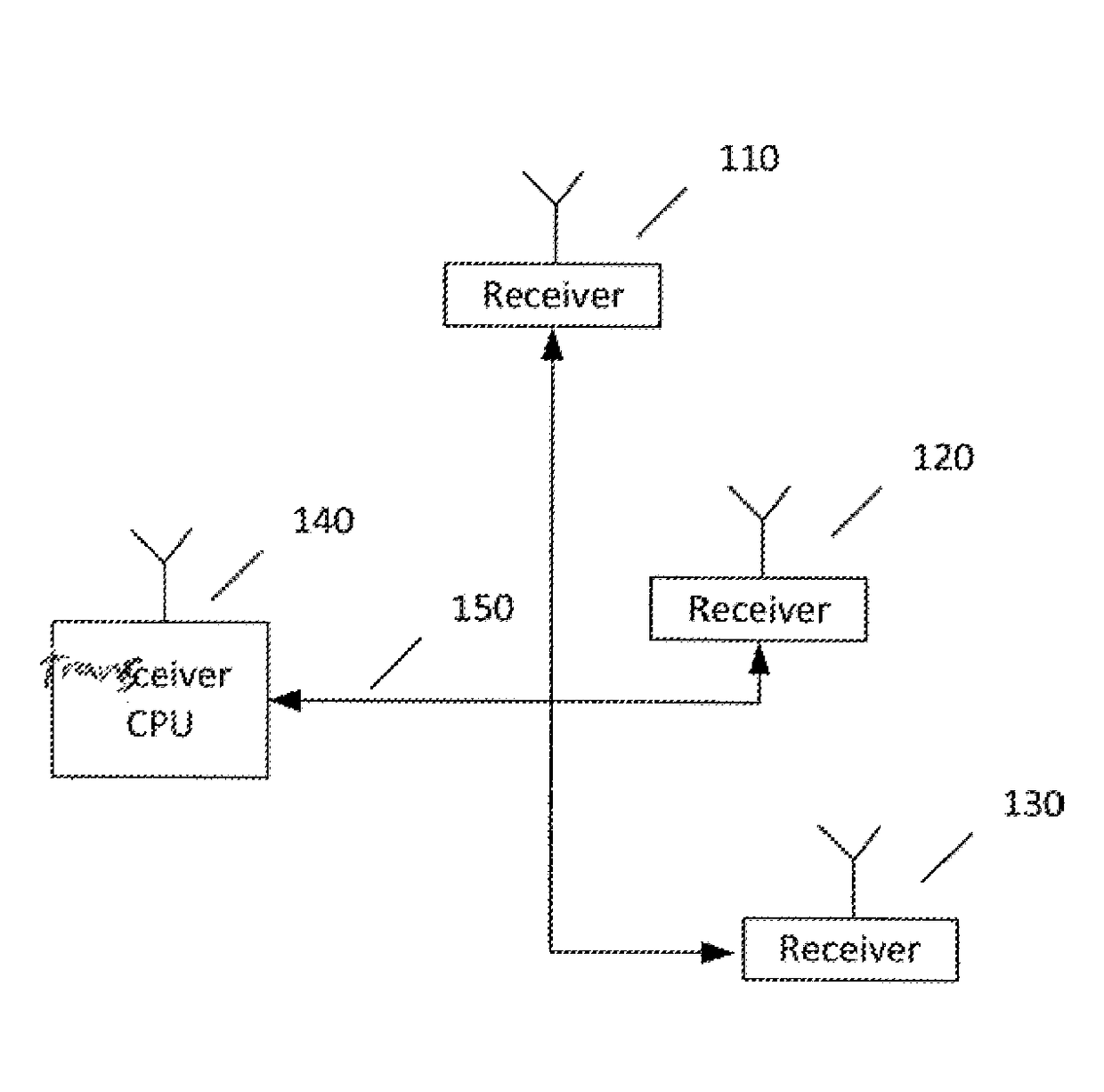
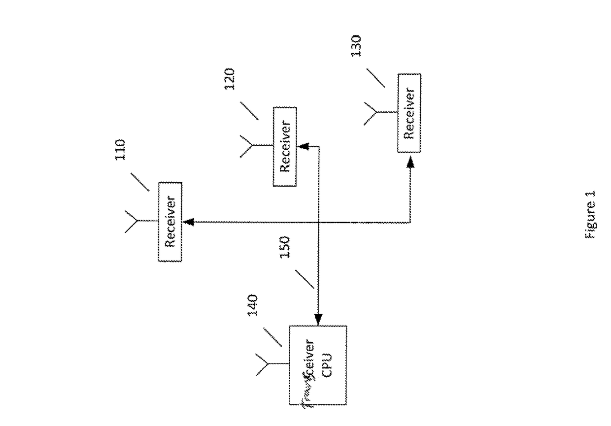
[0012]Certain embodiments of the present invention may provide a distributed antenna system that may utilize an array of monopole antennas with integrated receivers and digital signal processing (DSP) functionality at one or more of the antennas. The monopole antennas with integrated receivers and DSP functionality are herein referred to as “smart antennas.” The smart antennas may be mounted remotely from each other, but may still be networked together utilizing high speed Ethernet data busses such that the individual signals from each smart antenna can be summed in the appropriate phase relationship to form a directional antenna pattern. The signals can be simultaneously combined in multiple phase relationships such that bearing can be determined. The smart antennas may be installed in various spatial geometries to take advantage of improved installation locations.

[0013]The distributed antenna system according to certain embodiments of the present invention may provide maximum flex...


PUM


Abstract

Various communication systems may benefit from suitable antenna systems. For example, unmanned aircraft may benefit from systems and methods for providing a distributed airborne collision avoidance system antenna array. An apparatus can include a transceiver configured to transmit and receive avionics signals at a host vehicle. The apparatus can also include an interface configured to communicate with an array of a plurality of avionics receivers, wherein the avionics receivers are configured to receive the avionics signals at the host vehicle.

Description

CROSS-REFERENCE TO RELATED APPLICATION[0001]This application is related to and claims the benefit and priority of U.S. Provisional Patent Application No. 62 / 233,868, which was filed Sep. 28, 2015, titled “SYSTEMS AND METHODS FOR PROVIDING A DISTRIBUTED AIRBORNE COLLISION AVOIDANCE SYSTEM ANTENNA ARRAY,” which is hereby incorporated herein by reference in its entirety.BACKGROUNDField[0002]Various communication systems may benefit from suitable antenna systems. For example, unmanned aircraft may benefit from systems and methods for providing a distributed airborne collision avoidance system antenna array.Description of the Related Art[0003]Traditional Traffic Alert / Collision Avoidance System (TCAS) directional antennas are comprised of an array of precisely spaced radiating elements contained within a radome. The spacing of the elements is largely determined by the frequency of operation and the desired radiation pattern. Current TCAS antennas also require an optimal location on an ai...

Claims


Application Information

Patent Timeline
Patent Type & Authority Applications(United States)
IPC IPC(8): G01S3/02G01S3/48G08G5/04H01Q1/28G01S13/933
CPCG01S3/023G01S3/48H01Q1/28G08G5/04G01S13/781G08G5/0008G08G5/0021G08G5/0078G08G5/045G08G5/0052H04L67/00G01S13/933G01S5/0027
Inventor MCCULLEN, ROBERT J.SMITH, MARK D.
Owner AVIATION COMM AMP SURVEILLANCE SYST LLC
Why Eureka
Try Eureka