Radar detector for recognizing user's motion

a technology of user's motion and radar detector, which is applied in the field of electronic devices, can solve the problems of affecting the safety of driving a vehicle, and the movement of the driver for handling the radar detector, so as to enhance the convenience of using a product, facilitate handling, and hinder the effect of safe driving

Active Publication Date: 2017-10-19
JJ
View PDF2 Cites 11 Cited by
  • Summary
  • Abstract
  • Description
  • Claims
  • Application Information

AI Technical Summary

Benefits of technology

[0026]The present invention implements a radar detector which can be easily handled by a vehicle driver while driving through a simple motion of a hand gesture without hindering safe driving of a vehicle when an output sound of sensing radar (or a laser) is not needed.
[0027]In addition, the present invention implements a radar detector which can enhance convenience of using a product and guarantee safety of a user while driving by designing a new method and sensor device for switching an output sound of the radar detector to a mute state or reducing the output sound to a small sound of a predetermined level.
[0028]In addition, the present invention may correct malfunctions of a radar detector and allow a user to arbitrarily add (or delete) an alert rejection area or an alert area in an environment interfered by undesired signals, such as an area of severe radio interference, a downtown area where various signals are generated or the like, by additionally mounting a GPS receiving unit to the radar detector and utilizing position information of a GPS or a GLONASS.
[0029]The radar detector according to the present invention is expected to enhance convenience of a driver in handling the radar detector and contribute to safe driving by preventing traffic accidents.

Problems solved by technology

As is well-known how dangerous it is to handle a navigator or a cellular phone while driving, in the case a radar detector, a driver's behavior of lowering audio sound or operating various functions using a button unit 600 while driving may act as a factor inviting a great danger to safe driving of the driver according to road conditions and driving situations.
Particularly, latest vehicles have a serious problem in safety such that since the distance between the driver's seat and a device (the radar detector) placed on the dashboard or the windshield glass is long, movement of a driver for handling the radar detector increases, and keeping eyes ahead is neglected or even the movement can be applied to the steering wheel in the process of applying a handling force.
In the prior art, measures required for safety of a user when a driver should operate a radar detector while driving a vehicle are insufficient.
When the radar detector senses a speed sensor or aurally informs the driver of road conditions or states, if the aural signal is too loud or lasts for an extended period of time, it may act as a factor hindering the driving.
Like this, an operation of handling (driving) the radar detector by a driver acts as a factor hindering safe driving of the driver.
Although there are cases when an auto-mute function is applied for the convenience of drivers, it is insufficient to satisfy the requests and characteristics of various drivers since the auto-mute function is a convenience function executed only when a predetermined time is elapsed.
In addition, if the inner space of a vehicle is large or the vehicle is a large vehicle, the radar detector is placed at a place hard to operate by the driver or installed at a hidden place in many cases.
Even in this case, the problem of threatening safety of a vehicle may occur due to unnatural handling of a button by the driver.
In addition, a conventional radar detector has a problem in that it cannot distinguish a normal signal (e.g., an electromagnetic signal or the like of a speed meter or a safety alert transmitter) from undesired signals in an environment interfered by the undesired signals, such as an area of severe radio interference, a downtown area where various signals are generated or the like, and malfunctions of the radar detector frequently occur due to the interference of the signals.

Method used


Image

  • Radar detector for recognizing user's motion
  • Radar detector for recognizing user's motion
  • Radar detector for recognizing user's motion

Examples


Embodiment Construction

[0040]Hereinafter, preferred embodiments of the present invention will be described with reference to the drawings.

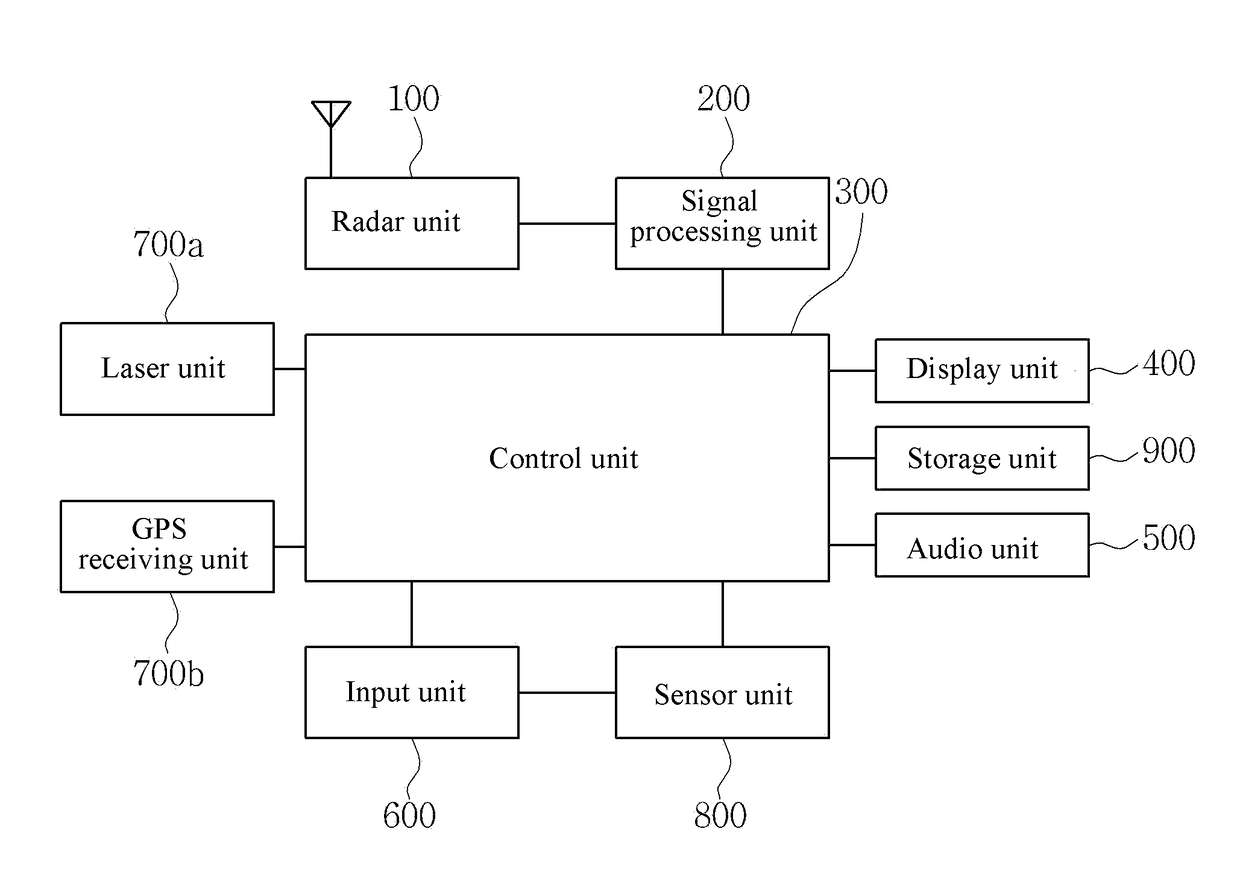
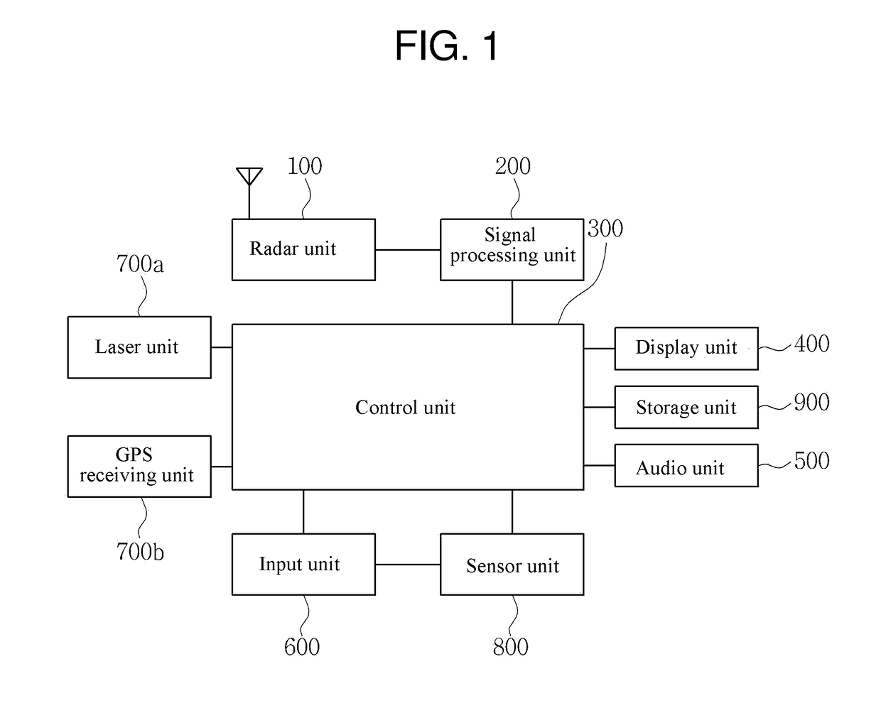
[0041]If a signal is received through a radar unit (or a laser unit), a radar detector outputs a sound of a predetermined message, and in some cases, the sound acts as a noise to a user (e.g., a driver) since the sound output events are frequently generated. The present invention implements a radar detector which can reduce the sound level of the radar detector or operate a mute function through a simple action or motion of the user when it is desired to block output of the sound of the radar detector generated so frequently.

[0042]In addition, the present invention corrects radar detecting errors generated in a registered area by registering areas where a signal detection error of the radar detector occurs, in advance or as needed, with reference to the position information of a GPS receiving unit, as well as a detection signal of the radar unit (or the laser unit). In ...


PUM


Abstract

Provided is a radar detector for detecting and recognizing, as a control signal, a hand gesture or a motion of a user and transferring the same to a peripheral device. The radar detector utilizes position information of GPS or GLONASS by additionally mounting a GPS receiving unit to the radar detector so as to amend malfunctions of the radar detector in environments in which interference from undesired signals may be received, such as areas of heavy jamming, downtown areas where various signals are generated, etc., and to enable a user to arbitrarily add (or delete) a notification refusal area or a notification area. The radar detector is expected to contribute to safe driving by increasing control convenience of a driver and preventing traffic accidents.

Description

TECHNICAL FIELD[0001]The present invention relates to an electronic device attached to a vehicle, and more specifically, to a radar detector.BACKGROUND ART[0002]Advanced countries such as USA, Japan and the like or other countries make a lot of efforts for the sake of safe driving of vehicles making use of various kinds of speed meters using microwaves or laser beams, i.e., radar, and safety alert transmitters for informing various situations of a road.[0003]Particularly, although speed meters and signal detectors are currently used for traffic enforcement purpose in some countries, the speed meters and the signal detectors are permitted to be used as legal devices for helping safe driving in USA, Japan and the like, and use of the speed meters and the signal detectors tends to be legalized across the world.[0004]With regard to the radar detector inducing safe driving of vehicles by detecting various signals as described above, various studies and patent applications are under progr...

Claims


Application Information

Patent Timeline
Patent Type & Authority Applications(United States)
IPC IPC(8): G01S13/56G01S13/88G01S13/86G01S19/13G01S7/06G01S17/04
CPCG01S13/56G01S13/86G01S7/06G01S13/886G01S19/13G01S7/022G01S17/04G01S13/66B60W50/08
Inventor SHIN, JIN WOOLEE, HYUN TAEKJANG, HEUNG CHULEUM, SANG WON
Owner JJ
Why Eureka
Try Eureka