Supercharge Your Innovation With Domain-Expert AI Agents!

Molten salt reactor

a reactor and salt technology, applied in nuclear reactors, nuclear elements, greenhouse gas reduction, etc., can solve the problems of depleting the earth's limited natural resources, not necessarily without shortcomings, and producing relatively large amounts of pollution and carbon dioxide gas

Active Publication Date: 2017-10-19
UTAH GREEN ENERGY TECH LLC
View PDF4 Cites 3 Cited by
  • Summary
  • Abstract
  • Description
  • Claims
  • Application Information

AI Technical Summary

Benefits of technology

The present invention is related to molten salt reactors and the systems and methods for their use. The described invention includes a graphite reactor core with a space inside that has fuel wedges with channels for fuel to pass through. The wedges can be made up of multiple sections that are coupled together. Alignment pins and seals can be used to keep the wedges aligned properly. The reactor core can be long and certain parts of the wedges and other reactor components can be easily replaced. The technical effects of the invention include improved performance and reliability of molten salt reactors.

Problems solved by technology

Although many conventional methods for generating electricity have proven to be useful, such methods are not necessarily without their shortcomings.
For instance, some methods that generate electricity by burning fossil fuels, also produce relatively large amounts of pollution and carbon dioxide gas, while depleting the Earth's limited natural resources.
Additionally, some methods for generating electricity via solar-power and / or wind-power systems are only able to generate electricity when they are exposed to a sufficient amount of sunlight and / or wind—factors that are not necessarily available 24 hours a day and 365 days a year.
Moreover, as some geothermal and hydroelectric power systems rely upon, and are limited by, the natural conditions on which such systems rely, many such systems are optimally (and sometimes only) placed in specific locations (e.g., at tectonic plate boundaries, rivers, reservoirs, coast lines, etc.) that have the requisite conditions.
Furthermore, some nuclear power plants also have shortcomings, which can include potential environmental damage associated with potential meltdowns, accident, uranium mining, and nuclear waste generated by the power plants.
Thus, while systems and methods currently exist that are used to generate electricity, challenges still exist, including those listed above.

Method used


Image

  • Molten salt reactor
  • Molten salt reactor
  • Molten salt reactor

Examples


Embodiment Construction

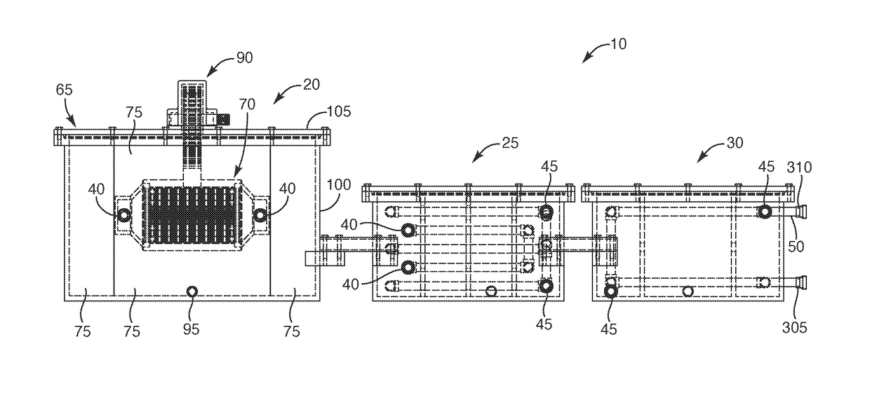
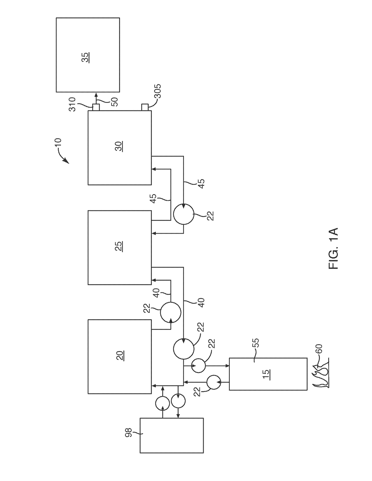
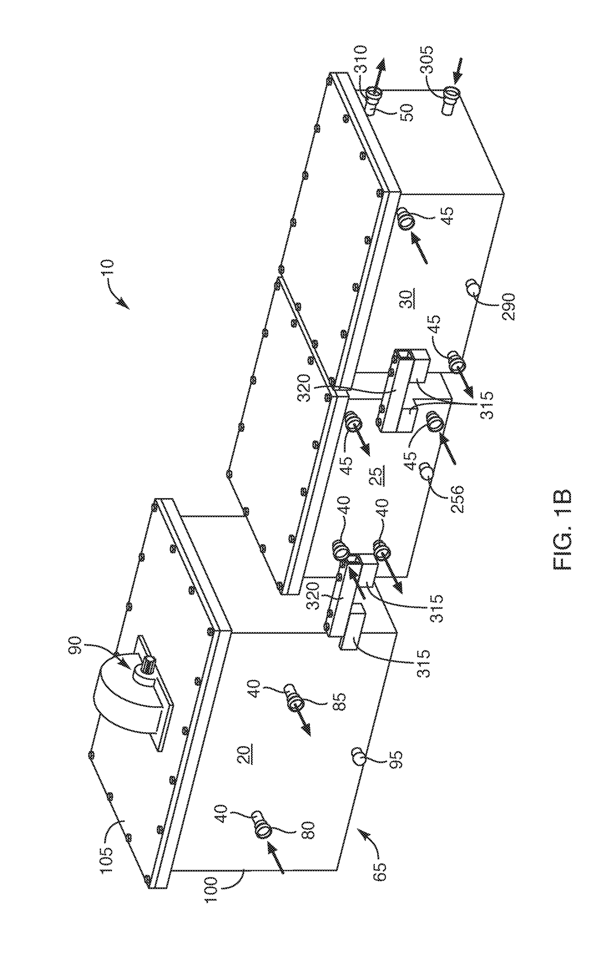
[0074]The present invention relates to molten salt reactors. More particularly, some embodiments of the described invention relate to systems and methods for providing and using molten salt reactors. While the described systems can include any suitable component, in some embodiments, they include a graphite reactor core defining an internal space that houses one or more fuel wedges, where each wedge defines one or more fuel channels that extend from a first end to a second end of the wedge. In some embodiments, one or more of the fuel wedges comprise multiple wedge sections that are coupled together end to end and / or in any other suitable manner. In some cases, one or more alignment pins also extend between two sections of a fuel wedge to align the sections. In some cases, one or more seals are also disposed between two sections of a fuel wedge. Thus, in some cases, the reactor core can be relatively long. Additionally, in some embodiments, one or more sections of the wedges and / or ...


PUM


Abstract

Systems and methods for providing and using molten salt reactors are described. While the systems can include any suitable component, in some cases, they include a graphite reactor core defining an internal space that houses one or more fuel wedges, where each wedge defines one or more fuel channels that extend from a first end to a second end of the wedge. In some cases, one or more of the fuel wedges comprise multiple wedge sections that are coupled together end to end and / or in any other suitable manner. In some cases, one or more alignment pins also extend between two sections of a fuel wedge to align the sections. In some cases, one or more seals are also disposed between two sections of a fuel wedge. Thus, in some cases, the reactor core can be relatively long (e.g., to be a pipeline reactor). Other implementations are also described.

Description

CROSS-REFERENCE TO RELATED APPLICATION[0001]This application claims priority to and is a continuation-in-part of U.S. application Ser. No. 14 / 859,100 (Attorney Docket No. 19094.10), filed Sep. 18, 2015, and entitled SYSTEMS AND METHODS FOR PROVIDING A MOLTEN SALT REACTOR, the entire disclosure of which is hereby incorporated by reference.FIELD OF THE INVENTION[0002]The present invention relates to molten salt reactors. More particularly, some implementations of the described invention relate to systems and methods for providing and using molten salt reactors. While the described systems can include any suitable component, in some implementations, they include a graphite reactor core defining an internal space that houses one or more fuel wedges, where each wedge defines one or more fuel channels that extend from a first end to a second end of the wedge. In some implementations, one or more of the fuel wedges comprise multiple wedge sections that are coupled together end to end and / o...

Claims


Application Information

Patent Timeline
IPC IPC(8): G21C3/32G21C3/54G21C3/336
CPCG21C3/32G21C3/336G21C3/54G21C1/16G21C1/22G21C5/02G21C5/126G21C19/14G21C19/19G21D9/00G21C7/00G21C11/06Y02E30/30G21C3/10
Inventor HANSEN, M SHELDON
Owner UTAH GREEN ENERGY TECH LLC
Features
  • R&D
  • Intellectual Property
  • Life Sciences
  • Materials
  • Tech Scout
  • Unparalleled Data Quality
  • Higher Quality Content
  • 60% Fewer Hallucinations
Learn More