Crystal resonator
a crystal resonator and resonator technology, applied in the direction of impedence networks, electrical devices, etc., can solve the problems of sudden frequency change, change in crystal impedance (ci), and difficulty in reducing unwanted responses
- Summary
- Abstract
- Description
- Claims
- Application Information
AI Technical Summary
Benefits of technology
Problems solved by technology
Method used
Image
Examples
second embodiment
[0044]The crystal element can be formed into various shapes. The following describes modifications of the crystal element.
[0045][Configurations of Crystal Resonator 200a and Crystal Resonator 200b]
[0046]FIG. 5A is a plan view of the crystal resonator 200a. The crystal resonator 200a includes a crystal element 210, the excitation electrodes 120, and extraction electrodes 221a. The crystal element 210 has square principal surfaces, and the mesa portions 111 are formed on the crystal element 210. The excitation electrodes 120 are formed on the mesa portions 111 on both principal surfaces of the crystal element 210. The extraction electrodes 221a are extracted from the respective excitation electrodes 120. While the crystal element 110 (see FIG. 2A) is formed into the rectangular shape, arranging the shape of the square crystal element 210, which has the short side length identical to the long side length, is also easy and the production cost can be reduced low, and thereby the crystal ...
third embodiment
[0060]The formation of an inclined portion whose surface is inclined at a peripheral area of an excitation electrode and a peripheral area of a mesa portion can also reduce the flexure vibration. The following describes a crystal resonator with the inclined portion.
[0061][Configuration of Crystal Resonator 500]
[0062]FIG. 8A is a plan view of the crystal resonator 500. The crystal resonator 500 includes a crystal element 510, which includes a mesa portion 511, excitation electrodes 520, and the extraction electrodes 121. The excitation electrode 520 is formed to have a circular shape identical to the excitation electrode 120 illustrated in FIG. 2A. The excitation electrode 520 includes a center portion 520a with constant thickness and an inclined portion 520b. The inclined portion 520b is formed at a peripheral area of the center portion 520a and has a thickness decreasing from the inner peripheral side to the outer peripheral side. FIG. 8A indicates the inside of the dotted line on ...
fourth embodiment
[0076]The excitation electrode may be formed to have various shapes. The following describes modifications of the excitation electrode.
[0077][Configuration of Crystal Resonator 600]
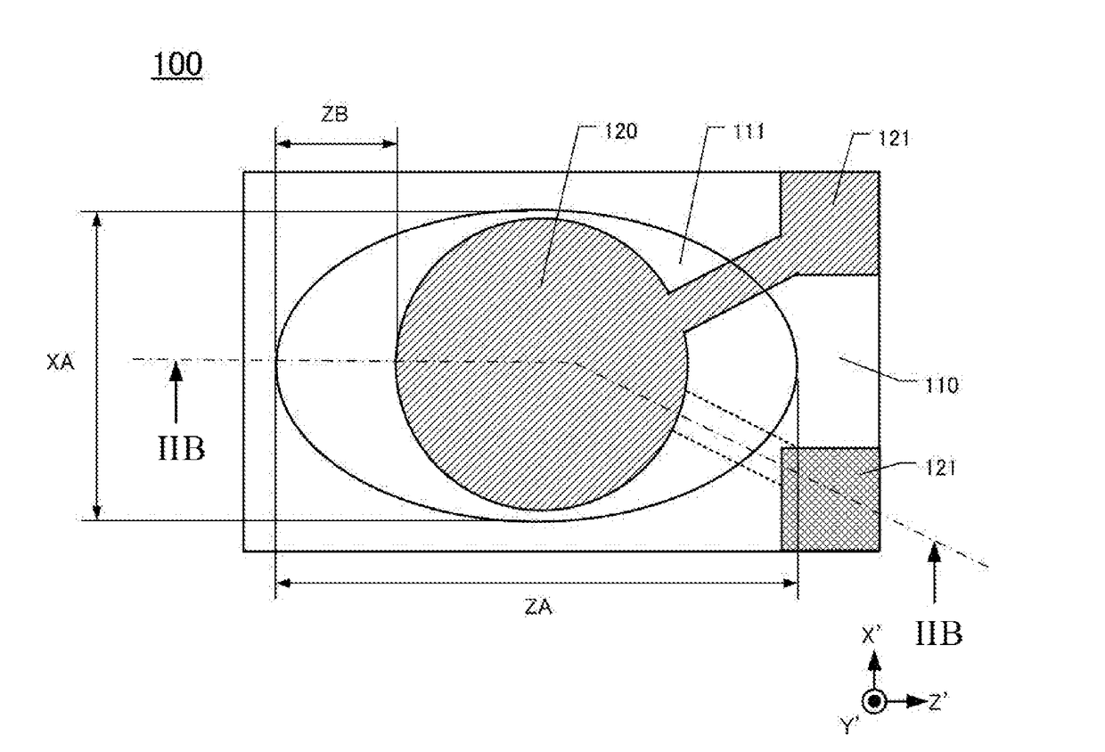
[0078]FIG. 10A is a plan view of the crystal resonator 600. The crystal resonator 600 includes the crystal element 110, excitation electrodes 620, and the extraction electrodes 121. The crystal resonator 600 differs from the crystal resonator 100 illustrated in FIG. 2A only in the shape of the excitation electrode. The excitation electrode 620 is formed to have the elliptical shape whose long axis extends in the Z′-axis direction and short axis extends in the X′-axis direction on the mesa portion 111. FIG. 10A denotes a length of the long axis of the excitation electrode 620 as ZE and a length of the short axis as XC.
[0079]While the circular excitation electrode 120 as illustrated in FIG. 2A can prevent the variation of and the increase in CI value, the elliptical excitation electrode further widens the a...
PUM
 Abstract
Description
Claims
Application Information
 - R&D
- Intellectual Property
- Life Sciences
- Materials
- Tech Scout
- Unparalleled Data Quality
- Higher Quality Content
- 60% Fewer Hallucinations
Browse by: Latest US Patents, China's latest patents, Technical Efficacy Thesaurus, Application Domain, Technology Topic, Popular Technical Reports.
© 2025 PatSnap. All rights reserved.Legal|Privacy policy|Modern Slavery Act Transparency Statement|Sitemap|About US| Contact US: help@patsnap.com


