Shaping apparatus and shaping method

a technology of shaping apparatus and shaping method, which is applied in the direction of manufacturing tools, instruments, optical elements, etc., can solve the problems of insufficient fabrication accuracy of parts, high roughness in surface finish, and slow processing speed, and achieve good processing accuracy and processing accuracy good

Active Publication Date: 2017-10-26
NIKON CORP
View PDF11 Cites 34 Cited by
  • Summary
  • Abstract
  • Description
  • Claims
  • Application Information

AI Technical Summary

Benefits of technology

[0012]According to this apparatus, it becomes possible to form a three-dimensional shaped object on the target surface with good processing accuracy.
[0013]According to a second aspect of the present invention, there is provided a shaping method of forming a three-dimensional shaped object on a target surface, comprising: controlling movement of the target surface and at least one of an irradiating state of a beam from a beam irradiation section including a condensing optical system and a supply state of a shaping material to be irradiated by the beam based on 3D data of the three-dimensional shaped object which is to be formed on the target surface, such that shaping is applied to a target portion on the target surface by supplying the shaping material while performing relative movement between the beam emitted from the beam irradiation section and the target surface, wherein intensity distribution of the beam within a predetermined plane on an exit surface side of the condensing optical system can be changed.
[0014]According to this method, it becomes possible to form a three-dimensional shaped object on the target surface with good processing accuracy.

Problems solved by technology

PBF substantially has some problems due to its shaping principle, such as; (1) insufficient fabrication accuracy of parts, (2) high roughness in surface finish, (3) slow processing speed, and (4) troublesome sintered metal powder handling that takes time and effort.

Method used


Image

  • Shaping apparatus and shaping method
  • Shaping apparatus and shaping method
  • Shaping apparatus and shaping method

Examples


Embodiment Construction

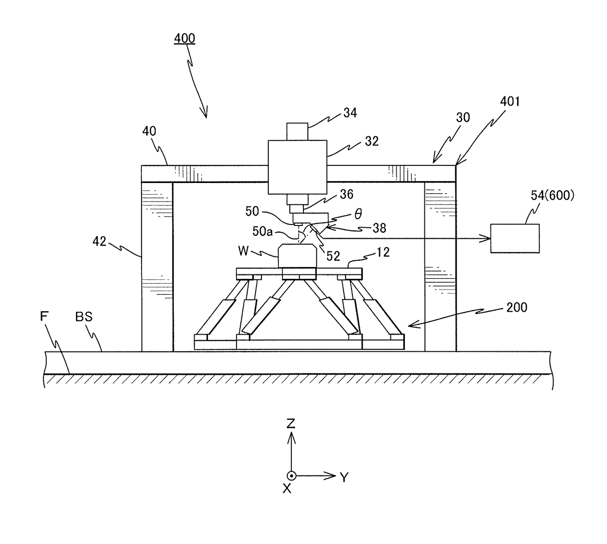
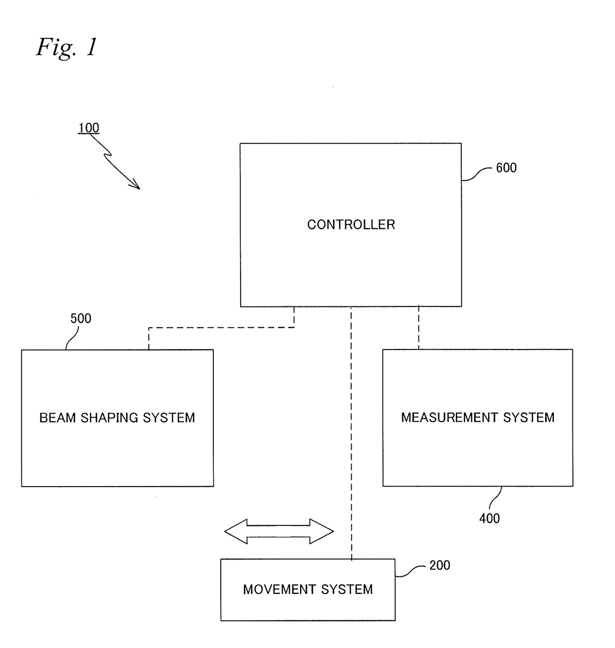
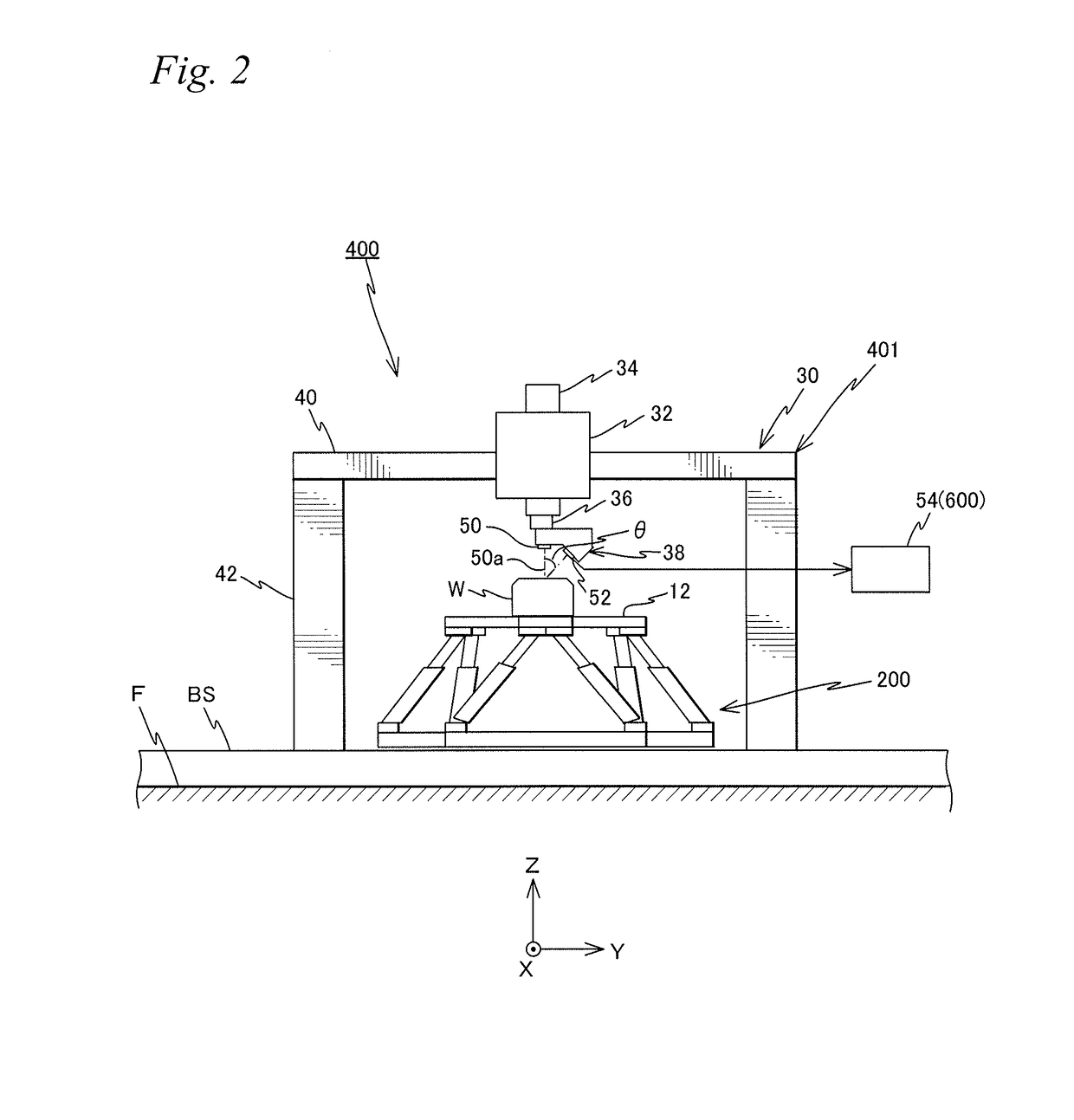
[0031]Hereinafter, an embodiment will be described with reference to FIGS. 1 to 15B. FIG. 1 is a block diagram showing an entire structure of a shaping apparatus 100 according to the embodiment.

[0032]Shaping apparatus 100 is a M3DP (Metal 3D printer) that employs DED (Directed Energy Deposition). Shaping apparatus 100 can be used to form a three-dimensional shaped object on a table 12 to be described later by rapid prototyping, as well as to perform additive manufacturing by three-dimensional shaping on a workpiece (e.g. an existing component). The present embodiment will focus on describing the latter case where additive manufacturing is performed on the workpiece. At the actual manufacturing site, it is common to make a desired component by further repeating processing on a component formed using a different manufacturing method, a different material, or a different machine tool, and the requirement is potentially the same for additive manufacturing by three-dimensional shaping.

[0...


PUM

PropertyMeasurementUnit
reflectanceaaaaaaaaaa
angleaaaaaaaaaa
angleaaaaaaaaaa

Abstract

A shaping apparatus is equipped with: a beam shaping system having a beam irradiation section that includes a condensing optical system which emits a beam and a material processing section which supplies a shaping material irradiated by the beam from the beam irradiation section; and a controller which, on the basis of 3D data of a three-dimensional shaped object to be formed on a target surface, controls a workpiece movement system and the beam shaping system such that a target portion on the target surface is shaped by supplying the shaping material from the material processing section while moving the beam from the beam irradiation section and the target surface on a workpiece (or a table) relative to each other. Further the intensity distribution of the beam in the shaping plane facing the emitting surface of the condensing optical system can be modified.

Description

CROSS-REFERENCE TO RELATED APPLICATIONS[0001]This application is a continuation of International Application PCT / JP2014 / 080150, with an international filing date of Nov. 14, 2014, the disclosure of which is hereby incorporated herein by reference in its entirety, which was not published in English.BACKGROUND OF THE INVENTIONField of the Invention[0002]The present invention relates to a shaping apparatus and a shaping method, and more particularly to a shaping apparatus and a shaping method to forma three-dimensional shaped object on a target surface. The shaping apparatus and the shaping method related to the present invention can be suitably applied when forming three-dimensional shaped objects by rapid prototyping (may also be called 3D printing, additive manufacturing, or direct digital manufacturing).Description of the Background Art[0003]Technology of forming a 3D (three-dimensional) shape directly from CAD data is called rapid prototyping (also may be called 3D printing, addit...

Claims


Application Information

Patent Timeline
Patent Type & Authority Applications(United States)
IPC IPC(8): B23K26/342B23K26/06B23K26/144B33Y10/00B33Y50/02B33Y30/00B23K26/08
CPCB23K26/342B33Y10/00B33Y30/00B23K26/144B23K26/0626B23K26/0665B23K26/08B33Y50/02G02B26/00G02F2203/12B22F2003/247Y02P10/25B22F12/44B22F10/66B22F12/53B22F12/22B22F10/25B22F12/90B22F12/41B22F10/362B22F12/45B33Y50/00
Inventor SHIBAZAKI, YUICHI
Owner NIKON CORP
Why Eureka
Try Eureka