Apparatus for generating steam

a technology of apparatus and steam, applied in the direction of boiler cleaning apparatus, lighting and heating apparatus, etc., can solve the problems of scale on the evaporation surface being subjected to thermal shock, breaking apart and dislodging, and evaporating quickly, so as to prevent water from reaching the scale collection region, quick evaporated

Active Publication Date: 2017-10-26
KONINKLJIJKE PHILIPS NV
View PDF9 Cites 20 Cited by
  • Summary
  • Abstract
  • Description
  • Claims
  • Application Information

AI Technical Summary

Benefits of technology

[0019]The evaporation surface may comprise one or more regions with recessed features. The evaporation surface may be provided with recessed regions, such as grooves or dimples, which will act to disturb any bias in the direction that water flows over the evaporation surface. It is advantageous to form a thin film of water over as much of the evaporation surface as possible as this will ensure the water is quickly evaporated, induces maximum thermal shock in any scale on the evaporation surface, and prevents the water from reaching the scale collection region. By providing the evaporation surface with one or more recessed regions the water flow will be spread out more and any prevailing flow will be disturbed and more evenly distributed.
[0020]The evaporation surface may comprise a wall having varying thickness such that, when the evaporation surface is heated or cooled during use, thermal expansion will cause the size and/or shape of the evaporation surface to change in an irregular manner to further assist in dislodging scale from the evaporation surface. In this way, the expansion and contraction of the evaporation surface will cause any scale formed on the evaporation surface to break apart and become dislodged, so that it can fall away from the evaporation surface.
[0021]In some embodiments, the apparatus may further comprise a scale collection chamber and a channel disposed such that when the apparatus is rotated from an operational position, in which water is provided to the evaporation surface, into a rest position, in which water is not provided to the evaporation surface, scale dislodged from the evaporation surface will pass along said channel into said scale collection chamber which is configured to retain said scale. In this way, dislodged scale can be moved from the vicinity of the evaporation surface and collected in the scale collection chamber which may be further from the evaporation surface where evapo

Problems solved by technology

As the film of water being fed onto the evaporation surface is cold relative to the heated evaporation surface, any scale on the evaporation surface will be subjected to thermal shock.
That is, the cooling effect of the water (at least until it evaporates) and the heating effect of the

Method used


Image

  • Apparatus for generating steam
  • Apparatus for generating steam
  • Apparatus for generating steam

Examples


Embodiment Construction

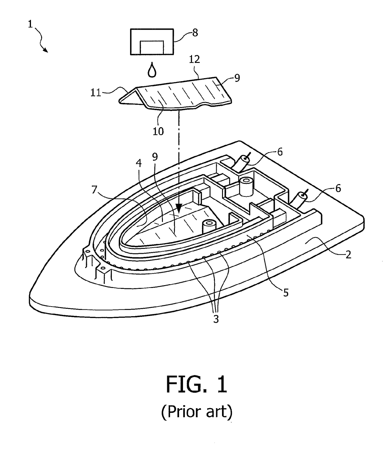
[0037]FIG. 1 shows a steam iron 1 which is known from patent document U.S. Pat. No. 5,613,309. The steam iron 1 comprises a soleplate 2 with a series of openings 3 through which steam can pass to be imparted onto garments being ironed. The steam iron 1 has a steam generating chamber 4 positioned centrally above the soleplate 2 and a steam channel 5 which extends around the soleplate 2 and connects the steam generating chamber 4 with the openings 3. A heating element 6 extends around the side edge 7 of the steam generating chamber 4 to evaporate water in the steam generating chamber 4.

[0038]The steam generating chamber 4 comprises a water drop dispensing device 8 that feeds water droplets from a water reservoir into the steam generating chamber 4 where the water is evaporated. The steam generating chamber 4 also includes a baffle device 9, which, for clarity, is shown positioned within the steam generating chamber 4 and also removed from the steam iron 1. The baffle device 9 has two ...


PUM


Abstract

The present application relates to apparatus for generating steam. It comprises a water inlet, a evaporation surface, and a heater disposed adjacent to the evaporation surface to heat the evaporation surface to a predetermined temperature such that water fed onto the evaporation surface via the water inlet forms a film on the evaporation surface and is evaporated. The apparatus is configured so that water is fed to one or more regions of the evaporation surface, and the temperature of the water fed onto the evaporation surface is lower than the predetermined temperature, so that scale on the or each region of the evaporation surface to which water is fed cools at a different rate at which water on a remainder of the evaporation surface cools. This causes scale on the evaporation surface to break apart and be dislodged from the evaporation surface.

Description

CLAIM OF PRIORITY[0001]This invention claims priority to, and the benefit of the earlier filing date of, that patent application filed on Dec. 30, 2015 and afforded Ser. No. 14 / 902,057, which claimed priority, as a National Stage filing of PCT / EP2014 / 065190 filed on Jul. 16, 2014 & International Application No. 13178049.6 filed on Jul. 25, 2013, the contents of all of which are incorporated by reference, herein.FIELD OF THE INVENTION[0002]This invention relates to an apparatus for generating steam, particularly but not exclusively to an apparatus for generating steam that may be incorporated into a device for applying steam to an article, such as a garment or linen.BACKGROUND OF THE INVENTION[0003]Many devices use steam to treat garments and other objects to remove wrinkles, for cleaning or for other purposes. For example, a steam iron discharges steam from a soleplate onto a garment to help remove wrinkles. In another example, a steam cleaner may comprise a hose with a steam applic...

Claims


Application Information

Patent Timeline
IPC IPC(8): F22B1/28D06F75/18F22B37/48F22B1/30
CPCF22B37/48F22B1/288F22B1/287F22B1/303F22B1/284D06F75/18F22B1/28
Inventor CHUA, HEE KENGCHING, BOON KHIANJIANG, YONG
Owner KONINKLJIJKE PHILIPS NV
Why Eureka
Try Eureka