
Air conditioning device having waterproof function

a technology of air conditioning device and function, which is applied in the direction of lighting and heating apparatus, ventilation system, heating type, etc., can solve the problems of difficulty and danger in maintaining electric equipment, affecting the efficiency of urban space use, and threatening the safety of citizens of the city, and achieves simple structure, low cost, and easy separation from the object

Inactive Publication Date: 2017-10-26
KANG EUN JIN +2
View PDF23 Cites 2 Cited by
  • Summary
  • Abstract
  • Description
  • Claims
  • Application Information

AI Technical Summary

Benefits of technology

The patent describes an air conditioning device that can be installed in an object with a closed inner space that requires both air conditioning and waterproofing. The device uses natural convection to maintain humidity and prevents water from flowing into the inner space during rainfall. The device includes a perforated pipe system that allows air and water to flow through while preventing them from flowing through the ventilation, supply, and exhaust pipes. This simplifies the structure of the device and allows for easy separation from the object, making it easier to repair and manage. The device also includes a plurality of perforated pipes to supplement the ventilation capacity and prevent overheat and excessive moisture. Additionally, the device includes a guide member to prevent shaking and a separate supply and exhaust fan to prevent overheat and unnecessary power consumption. The device can rapidly cool the inner space of the object and minimize power consumption by making the best use of cooling through natural convection.

Problems solved by technology

Conventionally, since electrical equipment such as a transformer, a switch, and a communication device is installed in an upper end of a large ground facility such as an electric pole, it was difficult and dangerous to maintain the electric equipment because an electric equipment manager had to climb the electric pole to maintain and repair the electric equipment.
As a result, the electrical equipment related facilities hurt beauty of the city, hindered an efficient use of urban space, and caused a threat to safety of citizens of the city.
However, since the electrical equipment is installed on the ground surface, the electrical equipment causes inconvenience of pedestrians and it is frequently reported that electrical equipment is flooded or damaged due to repeated rainy season and typhoon every year.
In addition, it is also frequently reported that a vehicle collides with the electrical equipment due to driver's carelessness.
Flooding or destruction of the electrical equipment causes fire, electric shock, explosion, or the like, thereby, leading to massive property loss and personal injury.
Since flooding of the electrical equipment leads directly to failure of the electrical equipment and accidents, waterproofing of the electrical equipment should be solved first when the electrical equipment is buried underground.
If the electrical equipment is installed in a sealed underground space for waterproofing the electrical equipment, the underground space where the electrical equipment is installed cannot be ventilated with outside air, and thus, not only it is not easy to release the heat generated from the electrical equipment, and but also it is difficult to maintain the same humidity as on the ground.
The facility can be installed on the ground such that the underground space where the electrical equipment is installed can be ventilated with outside air so as to maintain the heat and humidity of the electrical equipment, but there is a problem in which that the effect of the underground burial of the electrical equipment is not great because the ground facility also has the same problems as the electrical equipment.

Method used


Image

  • Air conditioning device having waterproof function
  • Air conditioning device having waterproof function
  • Air conditioning device having waterproof function

Examples


Embodiment Construction

Technical Problem

[0005]There is provided an air conditioning device which can simultaneously perform air conditioning and waterproofing of an inner space of an object at a low cost without installing a separate ground facility for waterproofing the inner space of the object and can be installed at the same height as a ground surface. The present invention is not limited to the aforementioned technical solutions, and another technical solution can also be derived from the following description.

Technical Solution

[0006]An air conditioning device according to an aspect of the present invention includes at least one ventilation pipe whose lower end is coupled to a peripheral surface of at least one vent of an object at the outside of the object so as to communicate with an inner space of the object, at least one perforated pipe which is installed to be erected on a flat outer surface of the object in parallel with the each ventilation pipe, a duct which is connected between upper ends of...


PUM


Abstract

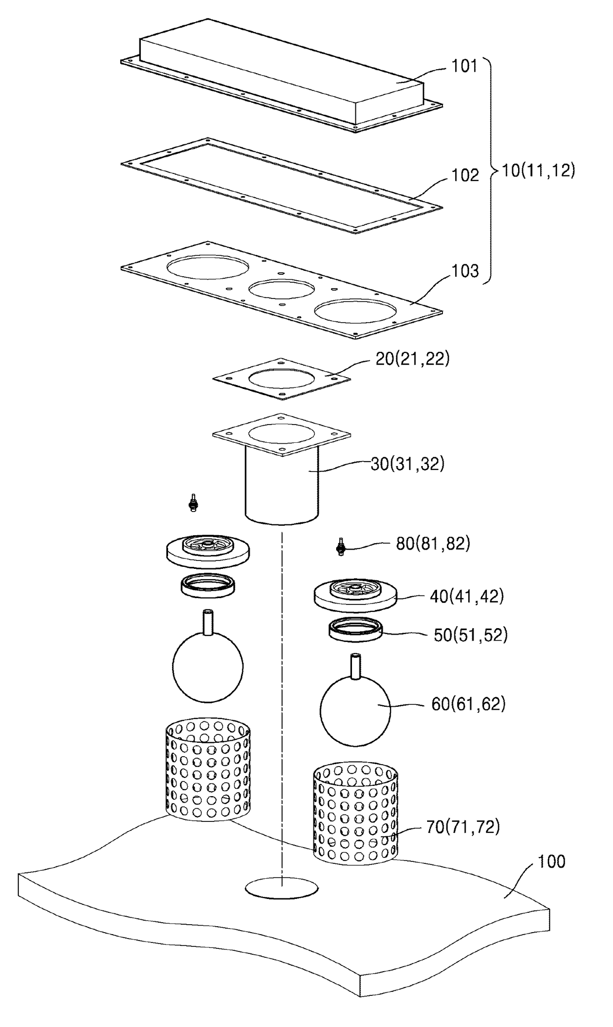
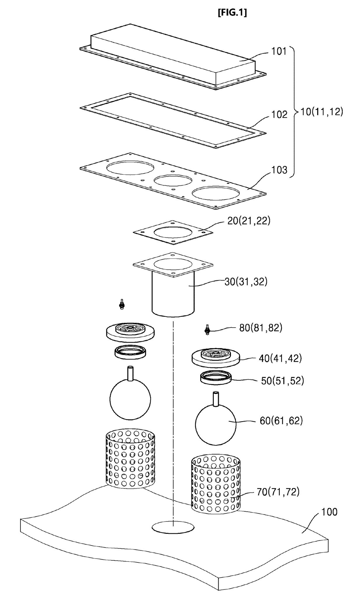
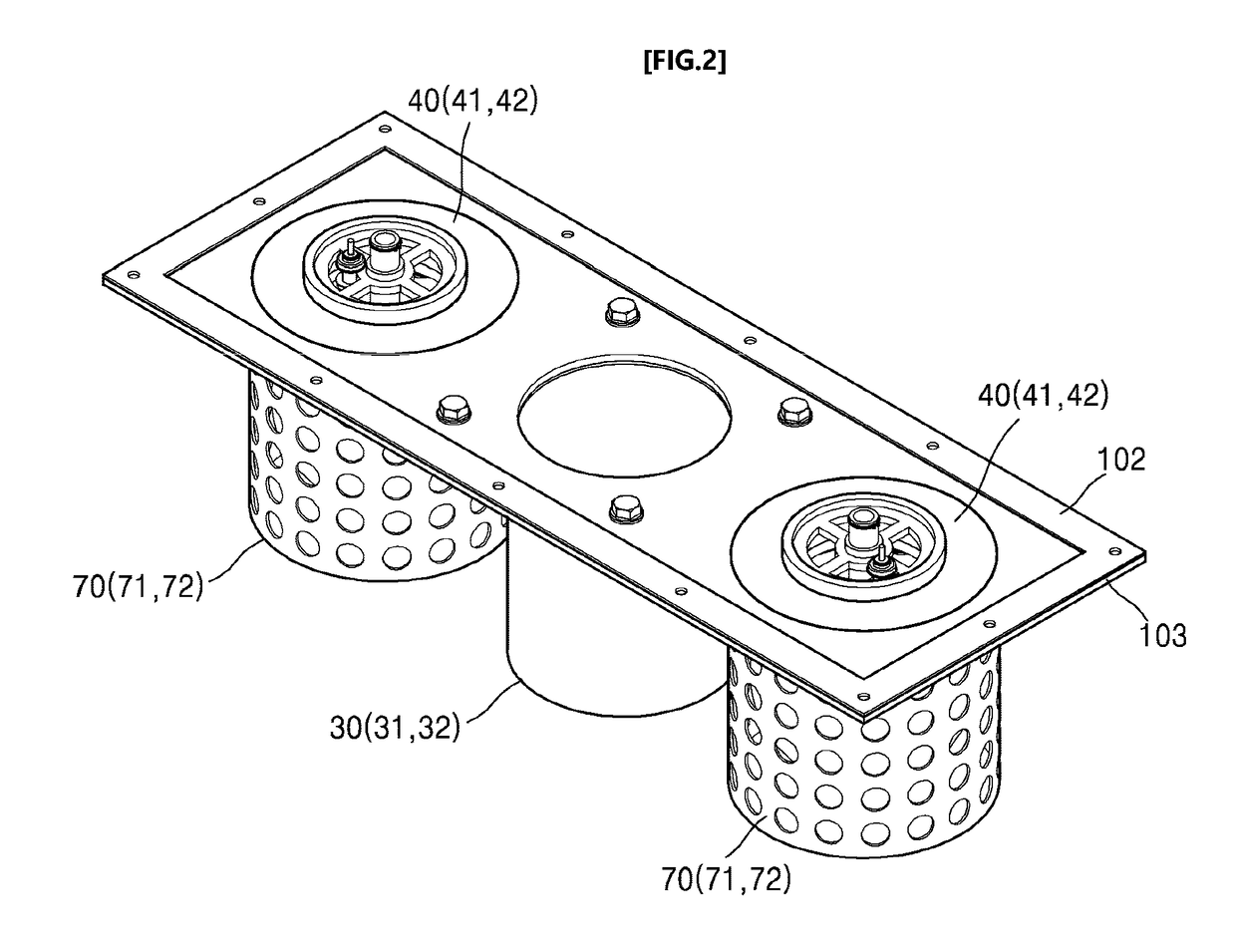
The present invention relates to an air conditioning device having a waterproof function, and includes a ventilation pipe whose lower end is coupled to a peripheral surface of a vent of an object at the outside of the object so as to communicate with an inner space of the object, a perforated pipe which is installed to be erected on a flat outer surface of the object in parallel with the ventilation pipe, a duct which is connected between an upper end of the ventilation pipe and an upper end of the perforated pipe such that the ventilation pipe and the perforated pipe communicate with each other, and a floating body which is positioned in the inner space of the perforated pipe and vertically moves in the inner space of the perforated pipe according to the amount of water flowing in through holes of the perforated pipe. A connection part between the perforated pipe and the duct is opened or sealed by means of vertical movement of the floating body such that the inner space of the object is ventilated with outside air through the ventilation pipe or the inner space of the object is closed.

Description

TECHNICAL FIELD[0001]The present invention relates to an air conditioning device which can simultaneously perform air conditioning and waterproofing of an inner space of an object.BACKGROUND ART[0002]Conventionally, since electrical equipment such as a transformer, a switch, and a communication device is installed in an upper end of a large ground facility such as an electric pole, it was difficult and dangerous to maintain the electric equipment because an electric equipment manager had to climb the electric pole to maintain and repair the electric equipment. In addition, demand for the electrical equipment explosively increases according to the rapid industrialization of modern society, and thereby, lots of electrical equipment related facilities such as the electric poles were installed all over the city. As a result, the electrical equipment related facilities hurt beauty of the city, hindered an efficient use of urban space, and caused a threat to safety of citizens of the city...

Claims


Application Information

Patent Timeline
Patent Type & Authority Applications(United States)
IPC IPC(8): F24F7/08F24F13/02F24F7/02F16L55/09B60H1/00F24F7/003
CPCF24F7/08F24F7/02B60H1/00F24F13/02F24F2007/001F16L55/09F16K24/046F24F7/003F24F7/04F24F7/06H02B1/56H05K7/20
Inventor KANG, EUN-JINLEE, GWANG-SEOKLEE, JANG-HYUK
Owner KANG EUN JIN
Learn More