Automatic cap-decap mechanism for reagent bottles

a technology of automatic cap decap and reagent bottle, which is applied in the direction of caps, applications, open containers, etc., can solve the problems of complex structure of cap decap action in refrigerated reagent station, and require more time and energy for the cap decap action, so as to optimize energy conservation and efficiency, improve work efficiency, and simplify the modular structure of the immunoanalyzer apparatus

Inactive Publication Date: 2017-10-26
TECHNOGENETICS HLDG
View PDF14 Cites 11 Cited by
  • Summary
  • Abstract
  • Description
  • Claims
  • Application Information

AI Technical Summary

Benefits of technology

[0023]The integration of the reagent station and of the automatic cap-decap mechanism makes the modular structure of the immunoanalyzer apparatus more simple and compact.
[0024]The automatic cap-decap mechanism provides the advantage that work efficiency is also improved.
[0025]In addition, in a closed reagent station, the automatic cap-decap mechanism will optimize energy conservation and efficiency, so that an easier and more reliable temperature control can be achieved.
[0026]Moreover, by assembling the automatic cap-decap mechanism with the reagent station, the reagent station can effectively maintain the refrigeration effect, and no additional complicated mechanical stru

Problems solved by technology

However, the mechanism to achieve cap-decap action in a refrigerated reagent station may

Method used


Image

  • Automatic cap-decap mechanism for reagent bottles
  • Automatic cap-decap mechanism for reagent bottles
  • Automatic cap-decap mechanism for reagent bottles

Examples


Embodiment Construction

[0048]In the framework of the present description, the automatic cap-decap mechanism for reagent bottles according to the present invention is applicable to an immunoanalyzer apparatus.

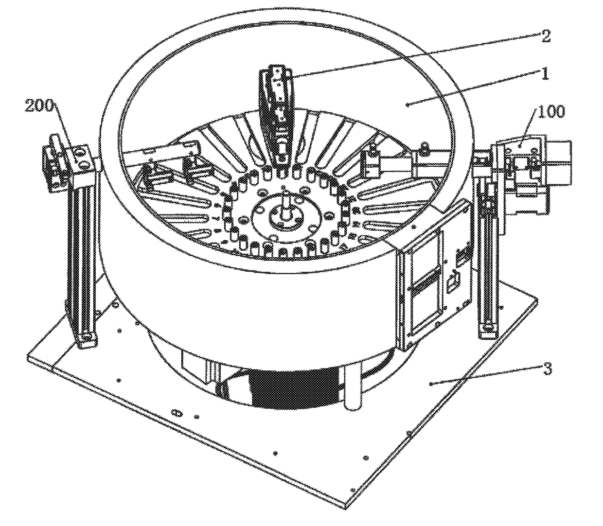
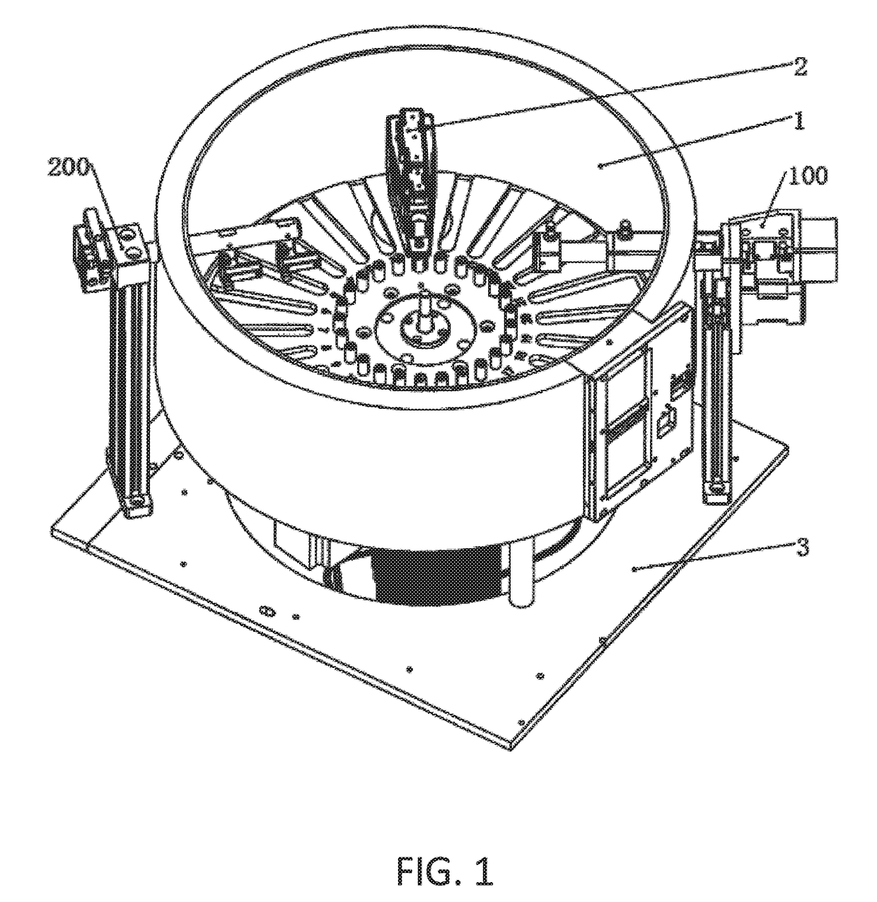
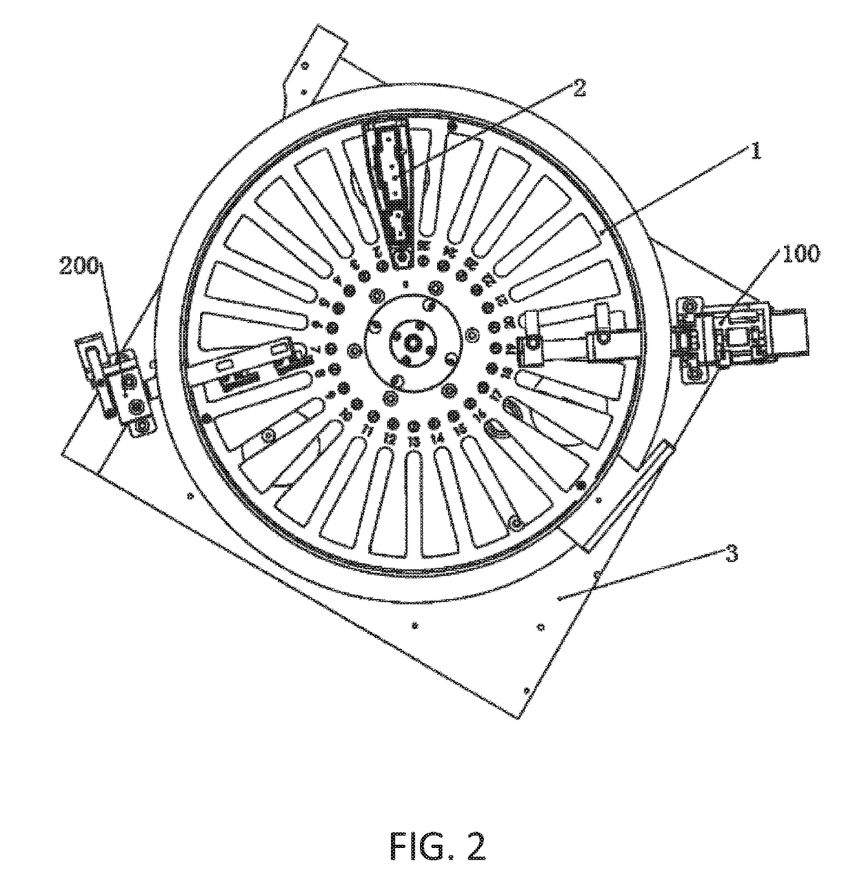
[0049]The integrated structure of the automatic cap-decap mechanism within a reagent station according to the present invention is shown in FIG. 1, FIG. 2 and FIG. 3.

[0050]FIG. 1 is illustrates the structure of the cap-decap mechanism for reagent bottles integrated within a reagent station. The automatic cap-decap mechanism for reagent bottles comprises a decap mechanism 100 and a cap mechanism 200. The decap mechanism 100 and the cap mechanism 200 on the reagent station 1, automatically cap and decap the reagent bottle 2. The reagent station 1 comprises a base 3. FIG. 2 is a top view of the reagent station 1. FIG. 3 is a side view of the cap reagent station 1.

[0051]FIG. 4 is an illustration of a reagent bottle and a snap joint, which are meant to cooperate and match. Subfigure (a) is an illustration ...


PUM


Abstract

The present invention relates to an automatic cap-decap mechanism for reagent bottles of an immunoanalyzer apparatus, comprising a decap mechanism (100) and a cap mechanism (200) in reagent station (1) of the immunoanalyzer apparatus; the decap mechanism (100) and the cap mechanism (200) are both configured for operating on a cap of a reagent bottle (2). The cap comprises a hinge-shaped plate cap (5), a snap joint (4) and a decap spring (6); one side of the hinge-shaped plate cap (5) is hinged on the reagent bottle mouth, and the other side of the hinge-shaped plate cap (5) comprises the snap joint (4); the snap joint (4) is configured for tightly clamping the hinge-shaped plate cap (5) on the reagent bottle mouth; one end of the decap spring (6) is mounted on a holding structure of the reagent bottle, and the other end of the decap spring (6) connects to a hinge pin of the hinge-shaped plate cap (5), so that when the snap joint (4) is not snapped in close position, the decap spring (6) is configured to move the hinge-shaped plate cap (5) so as to expose the bottle mouth in decap condition.
The decap mechanism (100) comprises: a first roller seat (104) located at the upper part of the reagent bottle (2), and a rotating rod (108) horizontally inserted into the roller bearings provided on the first roller seat (104), a first motor (103) for timely driving the rotating rod (108), and at least one first ejection rod (109) driven by the rotating rod (108) to move upward and downward; the first ejection rod (109) is configured for snapping the snap joint (4) in open position, so as to decap the reagent bottle (2).
The cap mechanism (200) comprises: a rocker (210) rotatably installed on the roller bearings of a rocker holder (209), and a knockout plate (204) connected on one end of the rocker (210); the knockout plate (204) comprises an electric magnet (203); the cap mechanism (200) further comprises at least one roller baffle (211) connected on the other end of the rocker (210), the roller baffle (211) comprising a roller (11) at the bottom, the knockout plate (204) being configured for acting on the rocker (210) under the action of a spring when the electric magnet (203) is not powered, so as to maintain the roller (11) of the roller baffle (211) on the hinge-shaped plate cap (5); the roller (11) is configured for snapping the snap joint (4) in close position, so as to cap the reagent bottle (2).
The present invention also relates to an immunoanalyzer apparatus and a regent bottle (2).

Description

TECHNICAL FIELD OF THE INVENTION[0001]The present invention relates to an automatic cap-decap mechanism for reagent bottles, to an immunoanalyzer apparatus, and to a reagent bottle for an immunoanalyzer apparatus.BACKGROUND ART[0002]An immunoassay is a biochemical test that measures the presence or concentration of a macromolecule in a solution through the use of an antibody and / or antigen. The macromolecule (often defined “analyte”) detected by the immunoassay is in many cases a protein. “Analytes” in biological liquids are frequently measured using immunoassays for medical and research purposes.[0003]Immunoassays may be performed by an apparatus defined as “immunoanalyzer”; such apparatus may carry multiple steps with one or more reagents being added and / or washed away or separated at different points in the assay.[0004]At present, to reduce evaporation of the reagents, an automatic immunoanalyzer is designed for reagent bottles or vials which comprise a cap. The cap is open (“dec...

Claims


Application Information

Patent Timeline
IPC IPC(8): G01N35/04B67B7/00B67B3/22B01L3/00G01N35/00
CPCG01N35/04B01L3/508B67B3/22G01N2035/0405B01L2300/042B01L2200/025G01N2035/00287B67B7/00B67B3/00
Inventor YU, CHAOSU, SHENGUANGTANG, QINGWENMELILLO, LUCA
Owner TECHNOGENETICS HLDG
Why Eureka
Try Eureka