Capacitive component having a heat-conducting connection element

Inactive Publication Date: 2017-11-02
ROBERT BOSCH GMBH
View PDF5 Cites 5 Cited by
  • Summary
  • Abstract
  • Description
  • Claims
  • Application Information

AI Technical Summary

Benefits of technology

[0008]Preferably, a surface region of the component facing a standing surface is embodied in a manner free of the connection element. As a result, the connection element may be formed expediently in terms of outlay by angling a plate.
[0009]In this regard, a small structural height of

Problems solved by technology

In power circuits having capacitors, heat

Method used


Image

  • Capacitive component having a heat-conducting connection element
  • Capacitive component having a heat-conducting connection element
  • Capacitive component having a heat-conducting connection element

Examples


Example

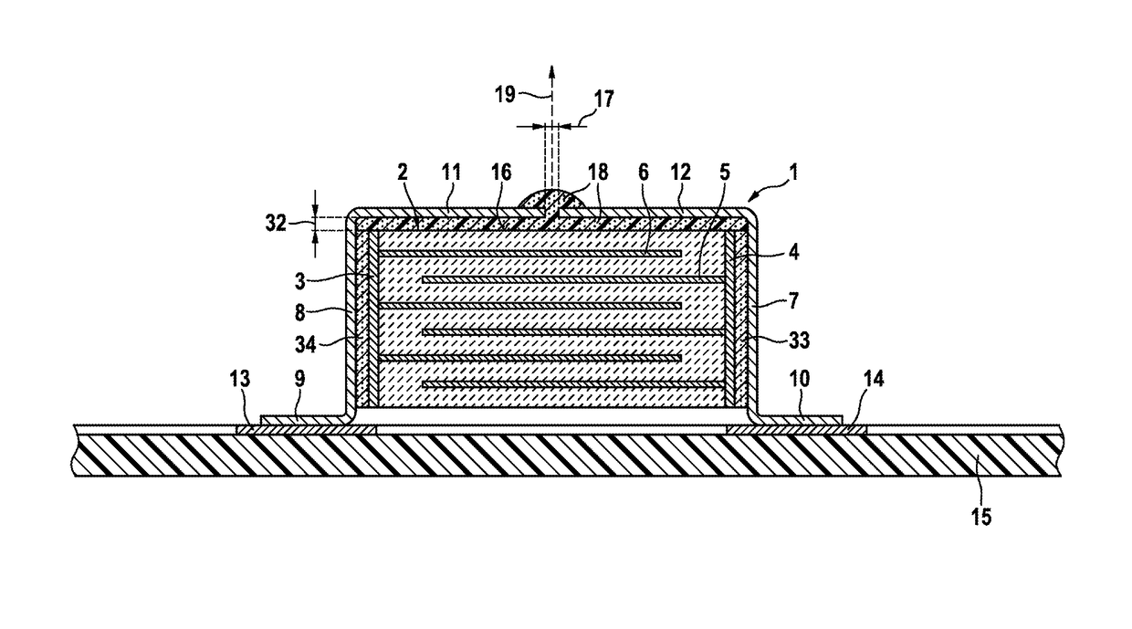
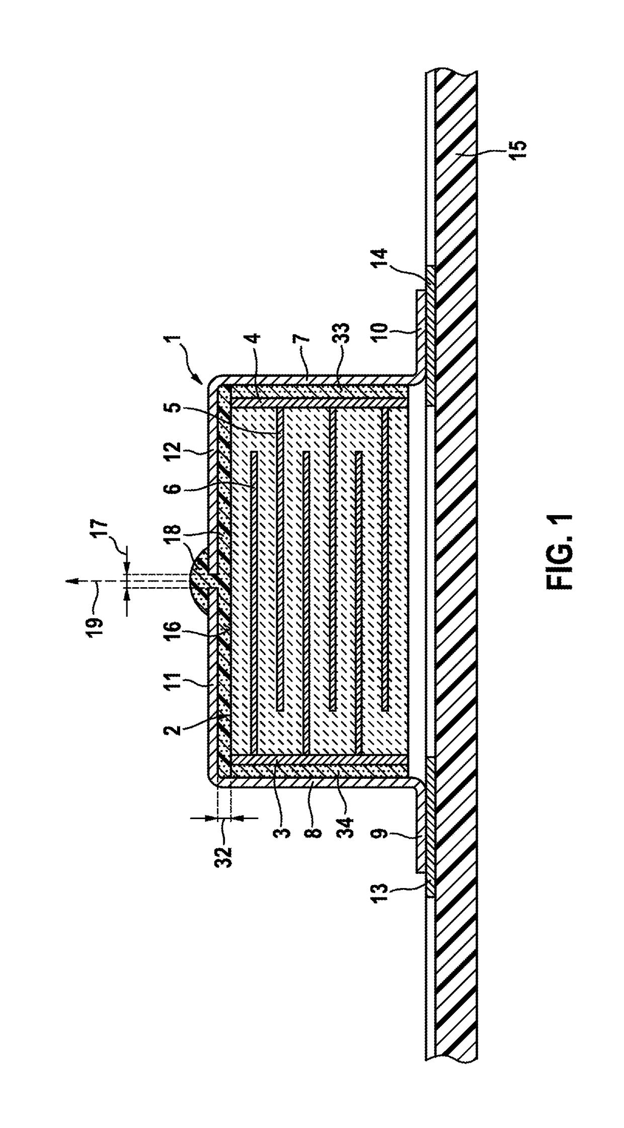
[0024]FIG. 1 shows one exemplary embodiment of a capacitively embodied component 1. The component 1 has a ceramically embodied capacitor 2. The capacitor 2 has two electrical connections extending parallel to one another, namely a connection 3 and a connection 4. The connections 3 and 4 are formed in each case by an electrically conductive layer, in particular a nickel-containing layer or a copper-containing layer. In this exemplary embodiment, the connection 3 is connected to a plurality of electrically conductive electrodes extending in each case into the interior of the capacitor 2, one electrode 6 of which is designated by way of example. In this exemplary embodiment, the connection 4 is connected to a plurality of electrodes extending in each case into the interior of the capacitor 2 and parallel to the electrodes, such as the electrode 6, which are connected to the connection 3. One electrode 5 of the electrodes connected to the connection 4 is designated by way of example. Th...


PUM

PropertyMeasurementUnit
Electrical conductivityaaaaaaaaaa
Electrical conductoraaaaaaaaaa
aaaaaaaaaa

Abstract

The invention relates to a capacitive component having a ceramic capacitor. The capacitor has two electrical connections, each of which is formed as an electrically conductive layer, wherein the connections are arranged in particular in parallel at a distance to one another, and including the capacitor between same. The capacitor has at least one connection element with a securing foot, wherein at least one connection is connected to the connection element in an electrically conductive and integrally bonded manner. According to the invention, the component has a surface region formed without connections. The connection element, in particular the connection plate, has at least one section which extends parallel to the connectionless surface region of the capacitor, and which is connected to the surface region in a heat-conducting manner, and is designed to conduct heat away from the surface region, and to direct same to the securing foot. The capacitor has preferably one gap extending between the section and the surface region, said gap being at least partially or entirely filled with an electrically insulating heat-conducting medium.

Description

BACKGROUND OF THE INVENTION[0001]The invention relates to a capacitive component comprising an in particular ceramically embodied capacitor. The capacitor has two electrical connections, wherein the electrical connections are embodied in each case as an electrically conductive layer, wherein the connections are spaced apart from one another—in particular in a parallel fashion—and enclose the capacitor between one another. The capacitor has at least one connection element, wherein at least one connection is electrically conductively and cohesively connected to the connection element, in particular a connection plate. The connection element preferably has a section forming a securing foot, in particular a standing foot.[0002]In power circuits having capacitors, heat loss is also generated in the capacitors. The heat loss can generally be emitted to the ambient air surrounding the capacitor or be dissipated by convection.SUMMARY OF THE INVENTION[0003]According to the invention, the com...

Claims


Application Information

Patent Timeline
IPC IPC(8): H01G2/08H01G4/224H01G2/06H01G4/12H01G4/30H01G4/232
CPCH01G2/08H01G4/232H01G4/224H01G4/30H01G4/12H01G2/06
Inventor PEUSER, THOMAS
Owner ROBERT BOSCH GMBH
Why Eureka
Try Eureka