
Fan motor for air conditioner

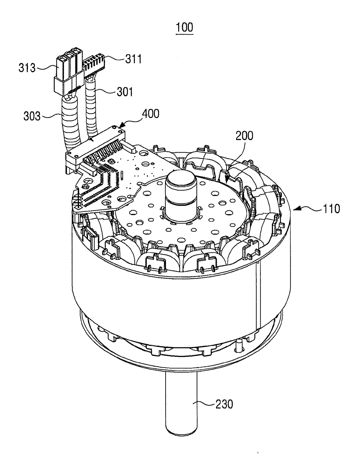
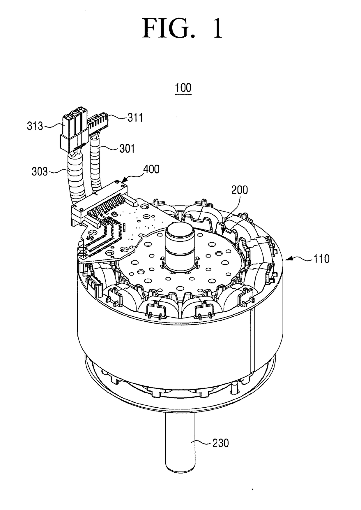
a technology for fan motors and air conditioners, applied in ventilation systems, magnetic circuit rotating parts, magnetic circuit shapes/forms/construction, etc., can solve the problems of reduced production reliability, reduced assembly workability, and increased cost due to lots of components, so as to improve soldering workability, facilitate wire insertion, and facilitate the effect of wire formation

Active Publication Date: 2017-11-02
SAMSUNG ELECTRONICS CO LTD
View PDF28 Cites 6 Cited by
  • Summary
  • Abstract
  • Description
  • Claims
  • Application Information

AI Technical Summary

Benefits of technology

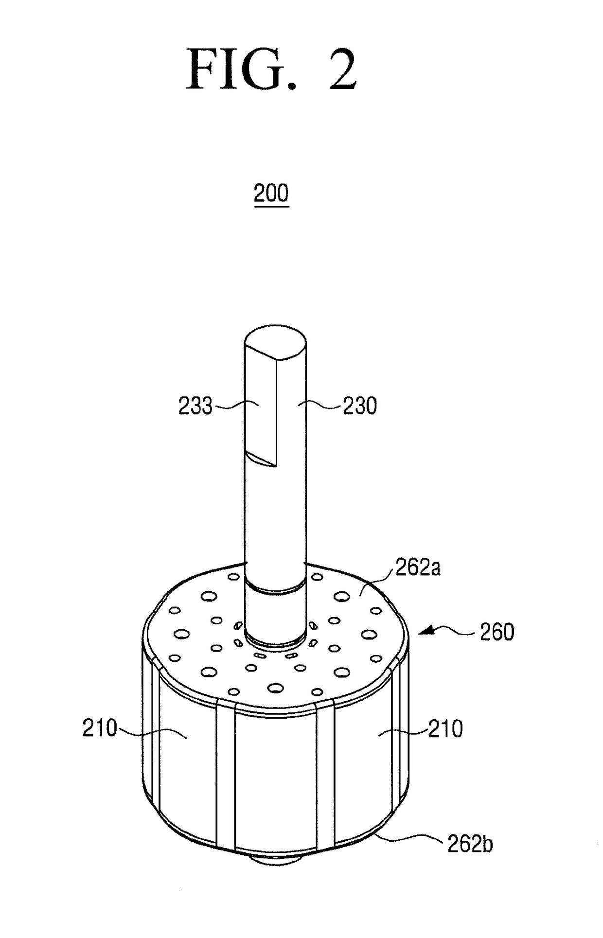
This patent describes a rotor structure for a fan motor that has strong bridges between the rotor shaft and the rotor core, which prevents the rotor core from scattering during operation. The rotor is made using a process called insert injection, which integrates the rotor core and shaft. The patent also describes a fan motor with a cable holder structure that makes wire insertion easier and improves soldering workability. Additionally, the fan motor has a cable holder structure that allows for easy wire formation and ensures that no additional insulation distance is necessary due to no wire protrusion.

Problems solved by technology

However, the bridge may support the whole weight of the rotor core and a rivet in such a structure and all the rotor cores may be scattered by the centrifugal force.
However, cost may be increased due to lots of components and assembly workability may be degraded due to the need for a high degree of dimensional tolerance between a diameter of a rivet and a diameter of a rivet hole formed in the rotor core.
However, a connector into which the wire is inserted is vulnerable to vibration and thus production reliability may be degraded.
The workability may be degraded due to difficulty in inserting the wire into the hole of the cable holder.
Additional insulation distance, which is inevitably ensured due to the wire protruding through the hole of the cable holder, may be an obstacle to miniaturization of the production.
Also, an exemplary embodiment is not required to overcome the disadvantages described above, and an exemplary embodiment may not overcome any of the problems described above.

Method used


Image

  • Fan motor for air conditioner
  • Fan motor for air conditioner
  • Fan motor for air conditioner

Examples


Embodiment Construction

[0035]Various embodiments will now be described more fully with reference to the accompanying drawings in which some embodiments are shown. The techniques described herein are exemplary, and should not be construed as implying any particular limitation on the disclosure. It should be understood that various alternatives, equivalents, and / or modifications could be devised by those skilled in the art. In the following description, unless otherwise described, the same reference numerals are used for the same elements when they are depicted in different drawings.

[0036]It will be understood that, although the terms first, second, etc. may be used herein in reference to elements of the disclosure regardless of an order and / or importance, such elements should not be construed as limited by these terms. The terms are used only to distinguish one element from other elements. For example, without departing from the spirit of the inventive concept, a first element may refer to a second element...


PUM


Abstract

A fan motor for an air conditioner includes a rotor shaft, a plurality of rotor cores arranged in a circumferential direction about a center of the rotor shaft, a bridge configured to couple the rotor cores, permanent magnets coupled to the plurality of rotor cores, and an insert-injected rotor body provided in a space formed through the rotor shaft, the rotor cores, the bridge, and the permanent magnets. A cable holder for the fan motor includes an upper cable holder in which a plurality of protrusion walls are formed downwardly, a lower cable holder in which a plurality of guide walls coupled between the plurality of protrusion walls are formed upwardly, and a soldering land which is formed in a lower portion of the lower cable holder and upon which a wire can be soldered.

Description

CROSS-REFERENCE TO RELATED APPLICATIONS[0001]This application claims priority from Korean Patent Application No. 10-2016-0053289, filed on Apr. 29, 2016, in the Korean Intellectual Property Office, the disclosure of which is incorporated herein by reference in its entirety.BACKGROUND1. Field[0002]Apparatuses and methods with respect to exemplary embodiments disclosed herein relate to a fan motor for an air conditioner, and more particularly, to a fan motor for an air conditioner in which a rotor core and a rotor shaft thereof are firmly integrated through insert injection and provides a cable holder with easier wire insertion and improved soldering workability.2. Description of the Related Art[0003]In general, air conditioners may be apparatuses used for cooling or heating rooms and may perform a cooling operation or a heating operation through characteristics that absorb surrounding heat in vaporization of a liquid refrigerant and release heat in liquefaction of the liquid refriger...

Claims


Application Information

Patent Timeline
IPC IPC(8): H02K16/02H02K5/22H02K1/27F24F7/007F24F1/38H02K7/14F24F1/00
CPCH02K16/02H02K1/2706H02K5/225F24F1/38F24F1/0003F24F7/007H02K7/14H02K1/274H02K1/28H02K1/2773H02K1/30H02K7/003H02K1/276
Inventor CHO, JIN-WOOKIM, NAM-SUSEO, UK-HOSEO, JONG-JUNHAN, JI-HOONHONG, MIN-WOOHWANG, WOONG
Owner SAMSUNG ELECTRONICS CO LTD
Learn More