Submersible pneumatic pump with air exclusion valve

Inactive Publication Date: 2017-11-09
BRESLIN MICHAEL KEVIN
View PDF6 Cites 2 Cited by
  • Summary
  • Abstract
  • Description
  • Claims
  • Application Information

AI Technical Summary

Benefits of technology

[0012]In accordance with one embodiment a submersible canister pump has a bottom-mounted inlet with a check valve for allowing liquid in, but not back out and a top-mounted outlet with a check valve for allowing liquid out, but not back in. The discharge pipe for the canister pump has a pipe tee at its base inside the pump. One end of the cross portion of the tee is attached to the bottom of the discharge pipe. The other end of the cross of the tee is attached to the inlet check valve. The 90° branch of the tee has an L-shaped fitting attached. The horizontal end of the L-shaped fitting is attached to the pipe tee on the bottom of the discharge pipe, while the vertical end faces upward with a cage, ball and seat on its open end. The ball has a lower specific gravity than water or any other liquid expected to enter the pump so that it floats on the liquid. The ball is captive in the cage

Problems solved by technology

However carefully timers are set when a pump is installed, changes in discharge hose back pressure, submergence, compressed air purity, and liquid viscosity can result in such timer settings being too long or too short.
Pneumatic timers are especially susceptible to failure and timing changes due to their dependence on the purity of compressed air and temperature.
It can also cause fume-laden compressed air to exhaust into the atmosphere at holding pond 20.
Further, it can cause turbulence in discharged liquid 29 in discharge hose 19 and at holding pond 20, which may cause adverse chemical reactions and unwanted solid suspension in discharged liquid 29.
Such lighter liquids can be flammable and contain harmful chemicals, such as benzene, that can dissolve in water.
Al

Method used


Image

  • Submersible pneumatic pump with air exclusion valve
  • Submersible pneumatic pump with air exclusion valve
  • Submersible pneumatic pump with air exclusion valve

Examples


Example

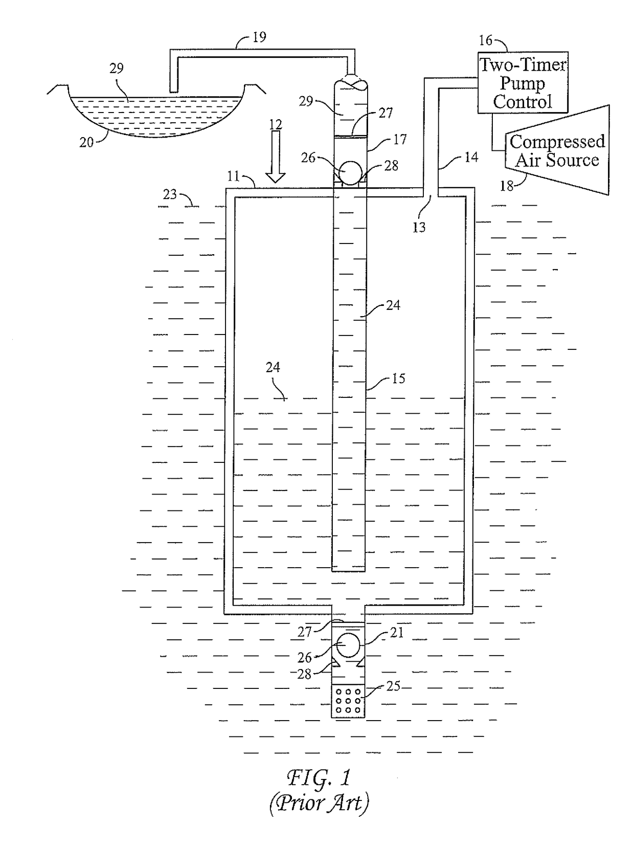
[0031]FIG. 1—Prior Art—Bottom-Loading Submersible Pneumatic Canister Pump

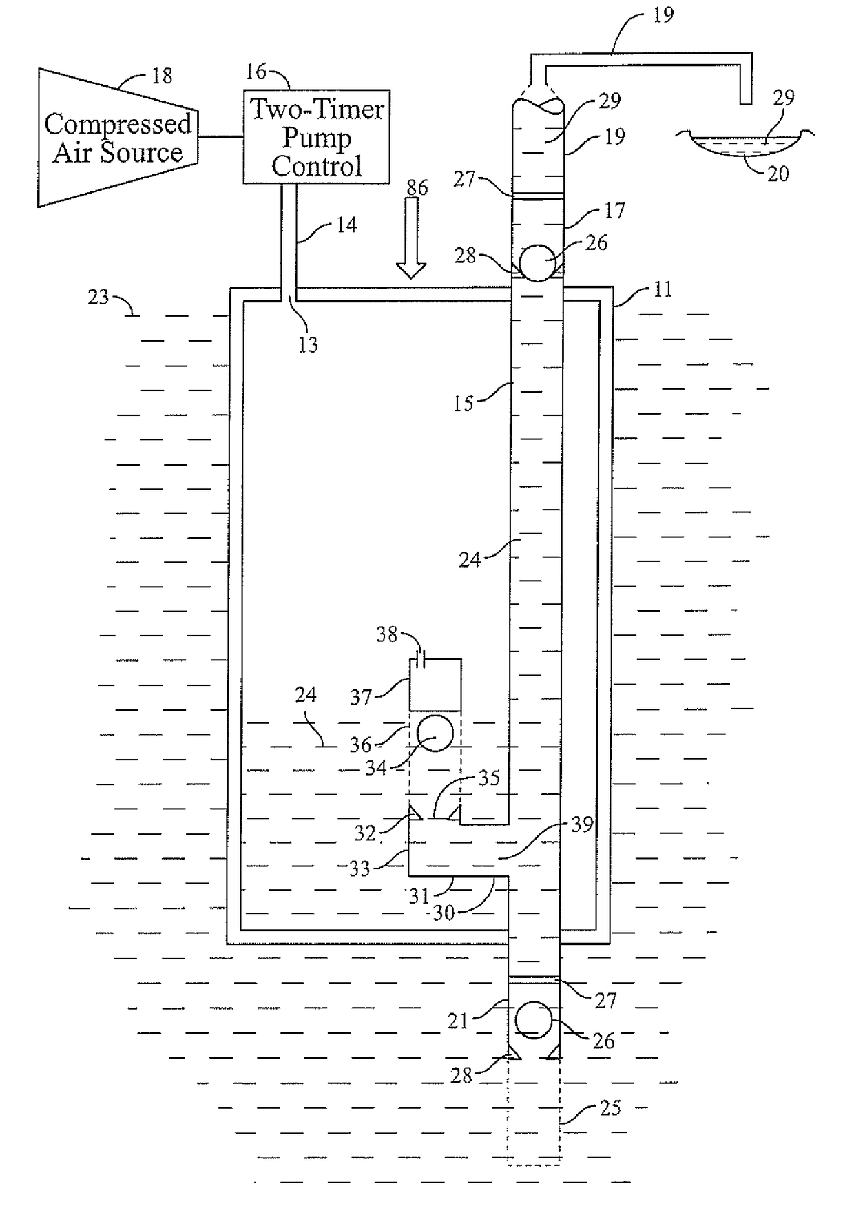
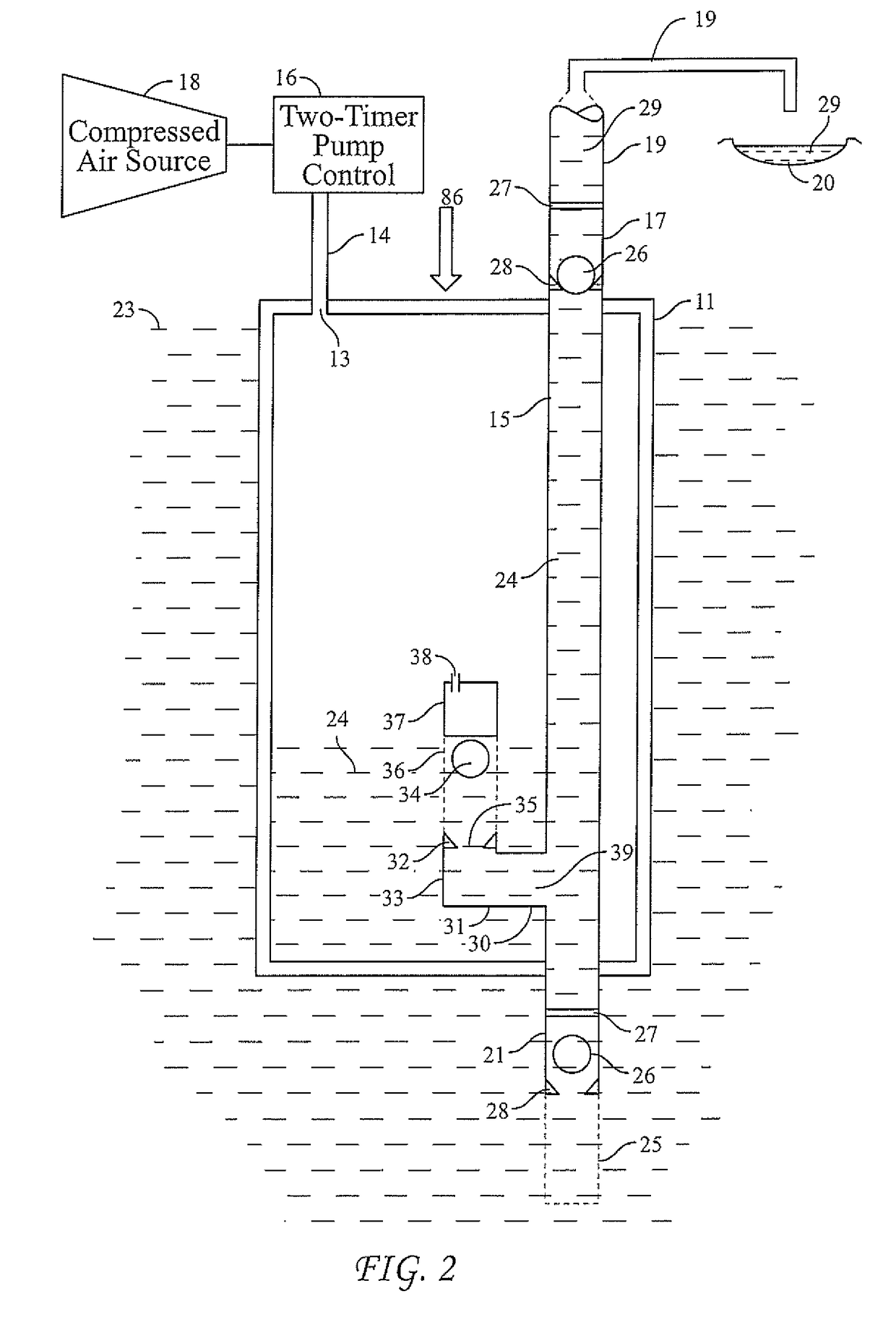
[0032]FIG. 1 shows a typical prior-art pneumatic submersible canister pump currently used in many industries; prior art pneumatic submersible canister pump 12 is submerged in exterior liquid 23 to be pumped. It consists of a sealed pump casing 11 with an upper and lower end, an interior and exterior and opening 13 for compressed air to enter and exhaust air to exit casing 11. An inlet check valve 21 allows exterior liquid 23 to enter casing 11, but does not allow interior liquid to be discharged 24 to exit. A discharge check valve 17 allows interior liquid 24 to exit casing 11, but does not allow discharged liquid 29 to enter. A discharge pipe 15 extends from near the bottom of casing 11 up through the top of casing 11 with discharge check valve 17 attached at the upper end. Liquid discharge hose 19 carries discharged liquid 29 from pump casing 11 to a discharge point, such as a liquid holding pond 20. A two-ti...


PUM


Abstract

A submersible pneumatic canister pump system for pumping liquid from a tank or underground location by incorporating a floating ball valve inside the pump for preventing air from exiting with the liquid discharge. The floating ball valve is located near the lower end of the pump and communicates with the discharge pipe. When liquid level approaches the lower end of the pump a ball of lighter density than the liquid rests on a seat and prevents further discharge of liquid and the passage of air out of the pump. Also shown are various pump control arrangements that can be used to operate the pump.

Description

BACKGROUND—PRIOR ART[0001]Pneumatically powered submersible pumps have been in use in many industries for many years for moving liquids from below ground or tanks to storage, treatment and / or disposal. Such pumps have the ability to move solids and operate in difficult environments where electric pumps may have problems. These types of canister pumps have been and are used to move sewage from collection points, or lift stations, to the sewage treatment plants. They have also been used for underground environmental remediation where electricity was not desired or available or the environment required special materials that were not easily incorporated into electric pumps. Such canister pump construction is fairly simple and their operation easy to understand. Such pumps can be operated and serviced with a minimal amount of training. Very few moving parts are in the pump, so they can be very reliable and easy to operate and service. Compressed air is often preferred over electricity a...

Claims


Application Information

Patent Timeline
IPC IPC(8): F04F1/06F16K1/14F16K15/04F16K31/20
CPCF04F1/06F16K31/20F16K15/04F16K1/14F04F1/08
Inventor BRESLIN, MICHAEL KEVIN
Owner BRESLIN MICHAEL KEVIN
Why Eureka
Try Eureka