Flow adjusting device

a technology of adjusting device and damping cylinder, which is applied in the direction of axle suspension, spring, cycle equipment, etc., can solve the problems of increasing the complexity of the system operation of the rider, affecting the safety of the rider, so as to improve the adjustability and simplify the adjustment

Active Publication Date: 2017-11-09
OHLINS
View PDF11 Cites 0 Cited by
  • Summary
  • Abstract
  • Description
  • Claims
  • Application Information

AI Technical Summary

Benefits of technology

[0035]According to one embodiment, a predetermined first relative rotational angle between the first and second annular member corresponds to the first position, wherein a flow of fluid through the variable fluid path is substantially free, and a predetermined second relative rotational angle between the first and second annular member angle corresponds to the second position, wherein the second flow of fluid is substantially blocked. The predetermined angles of the first and second position provides for ease of adjustability, as well as ease of use for the rider.
[0036]According to one embodiment, a variable flow of fluid through the variable fluid path is allowed for a relative rotational angle between the first and second annular member in a predetermined first range comprising the first position and substantially blocked for a relative rotational angle between the first and second annular member in a predetermined second range comprising the second position. In other words, apart from the defined first ...

Problems solved by technology

The movement of the wheel and vehicle is thus damped by the piston moving in the cylinder against the resistance of the fluid, which further causes damping fluid to move in the damping cylinder.
For applications in the field of mountain bikes, the special situation arises that efficient damping is associated with the pro...

Method used


Image

  • Flow adjusting device
  • Flow adjusting device
  • Flow adjusting device

Examples


Embodiment Construction

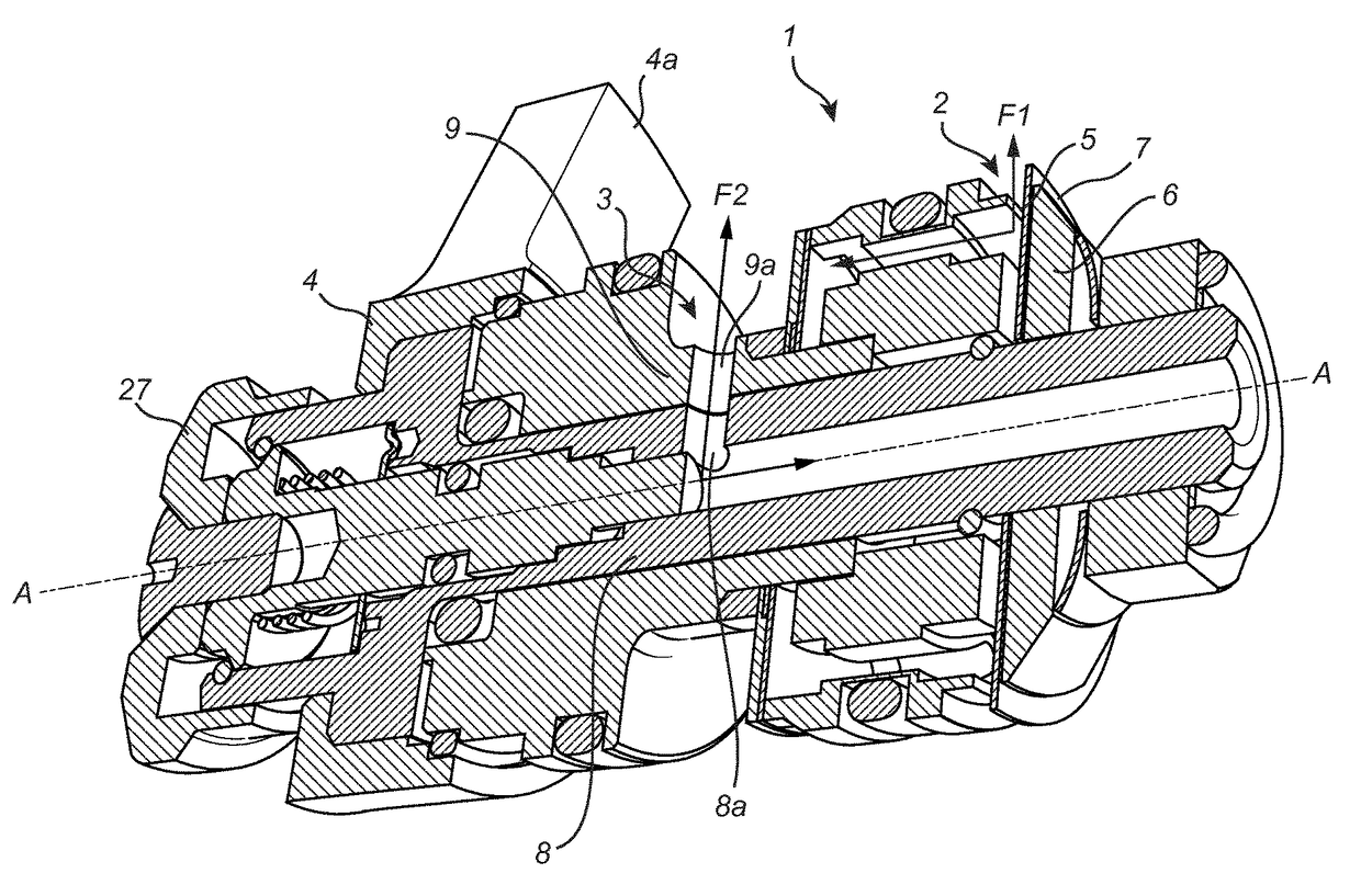
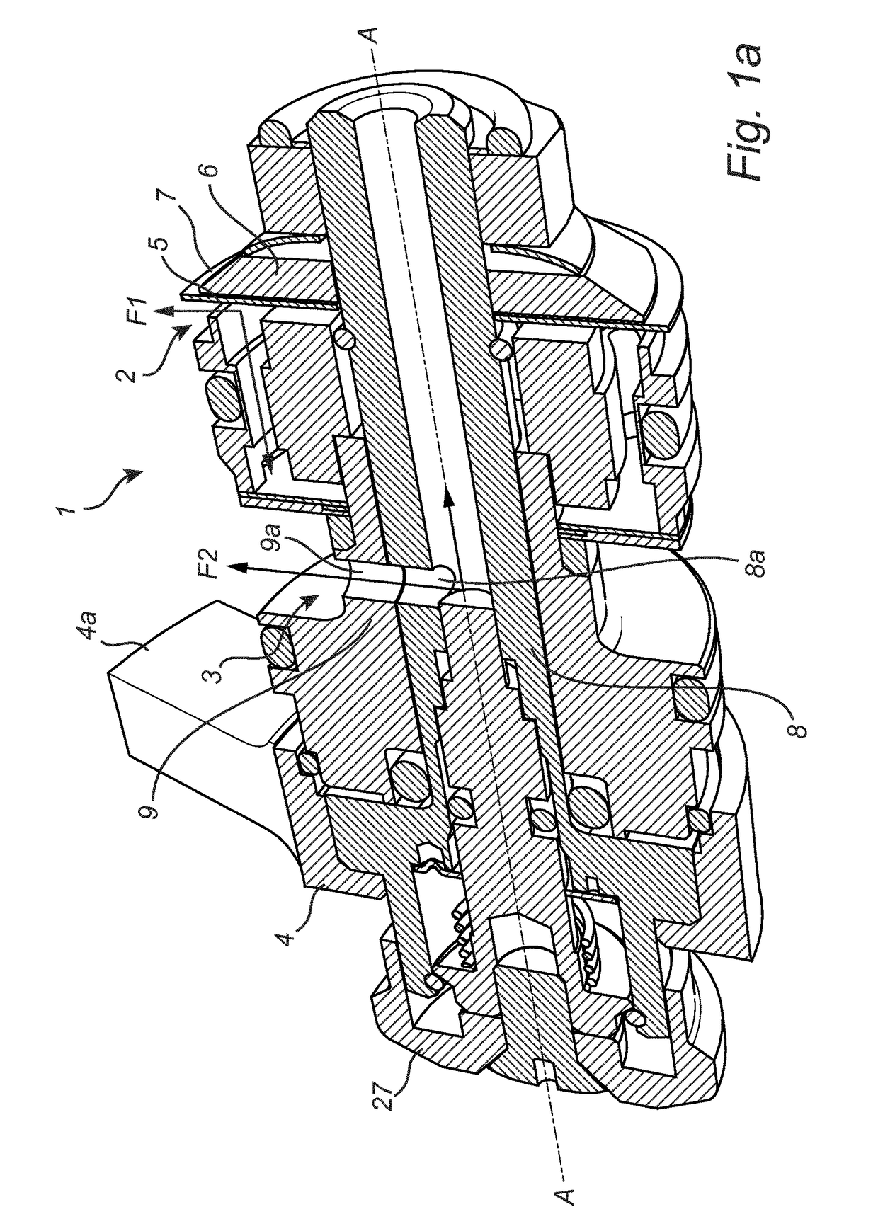
[0058]FIG. 1a shows a flow adjusting device 1 for adjusting a first flow of fluid F1 and a second flow of fluid F2. The flow adjusting device 1 comprises a first valve 2 adapted to control the first flow F1 and a second valve 3 adapted to control the second flow F2. The device 1 further comprises a flow adjustment element 4, comprising a handle 4a, adapted to adjust the first flow F1 and the second flow F2 simultaneously. The flow adjustment element 4 may be rotated with respect to the axis AA in order to adjust the flows.

[0059]The first valve 2 comprises a two-port valve disc 5, a clamp 6 and a shim 7. The shim 7 is arranged on between the valve disc 5 and the clamp 6 such that it may deflect around the edges of the clamp 6 in order to allow the first flow F1 to pass through the ports 5a, 5b of the valve disc 5. The clamp 6 is rotatatable with respect to the axis AA, in response to a rotation of the flow adjustment element. The functionality of the first valve 2 is described in fur...


PUM


Abstract

The present invention relates to a flow adjusting device (1) for a shock absorber for a vehicle, the shock absorber comprising a cylinder (21) and a piston (22) dividing the cylinder into at least a first and a second working chamber (23,24). The flow adjusting device is adapted to control at least a first damping medium flow (F1) and a second damping medium flow (F2) adapted to flow from at least one of the working chambers and comprises at least a first valve (2), adapted to control the first flow, and a second valve (3), adapted to control the second flow. The first valve and said second valve are jointly adjusted. The present invention further relates to a shock absorber comprising such a device and a front fork comprising such a shock absorber.

Description

TECHNICAL FIELD[0001]The present specification generally relates to the field of shock absorbers for vehicles and in particularly discloses a shock absorber comprising a flow adjusting device.TECHNICAL BACKGROUND[0002]Shock absorbers and damping systems are used for damping of the relative movement between the wheel and the chassis of a vehicle, such as a car, a motorcycle or a bicycle. A conventional shock absorber normally comprises a working cylinder filled with a damping fluid, such as hydraulic oil or gas, and a piston arranged in the cylinder. The damper may then be arranged to move telescopically between the vehicle chassis and the wheel. The movement of the wheel and vehicle is thus damped by the piston moving in the cylinder against the resistance of the fluid, which further causes damping fluid to move in the damping cylinder. In the specific case of a bicycle, or mountain bike, dampers may be arranged in a front fork arrangement and / or between the driver and the rear part...

Claims


Application Information

Patent Timeline
IPC IPC(8): F16F9/56F16F9/348F16F9/46B62K25/08B62K25/04
CPCF16F9/56F16F9/46B62K2025/047B62K25/08F16F9/348F16F9/461
Inventor SINTORN, TORKELJARL, JOHANLADUFJALL, ERIK
Owner OHLINS
Why Eureka
Try Eureka