Radiant burner for noxious gas incineration

a technology of noxious gas and burner, which is applied in the direction of incinerator equipment, combustion types, lighting and heating apparatus, etc., can solve the problems of premature failure of existing radiant burner sleeves or liners, and achieve the effect of reducing the fuel content and improving the warm-up time of the radiant burner

Pending Publication Date: 2017-11-09
EDWARDS LTD
View PDF7 Cites 1 Cited by
  • Summary
  • Abstract
  • Description
  • Claims
  • Application Information

AI Technical Summary

Benefits of technology

[0021]In one embodiment, the source is operable to supply the combustion materials in a substantially stoichiometric mix ratio when the temperature of the sintered metal fibre sleeve fails to exceed an operating temperature. Accordingly, a stoichiometric or fuel-rich mix ratio may be provided in order to improve the warm-up ...

Problems solved by technology

However, the first aspect also recognizes that these idle steps may be frequent and of short duration, and t...

Method used


Image

  • Radiant burner for noxious gas incineration
  • Radiant burner for noxious gas incineration
  • Radiant burner for noxious gas incineration

Examples


Embodiment Construction

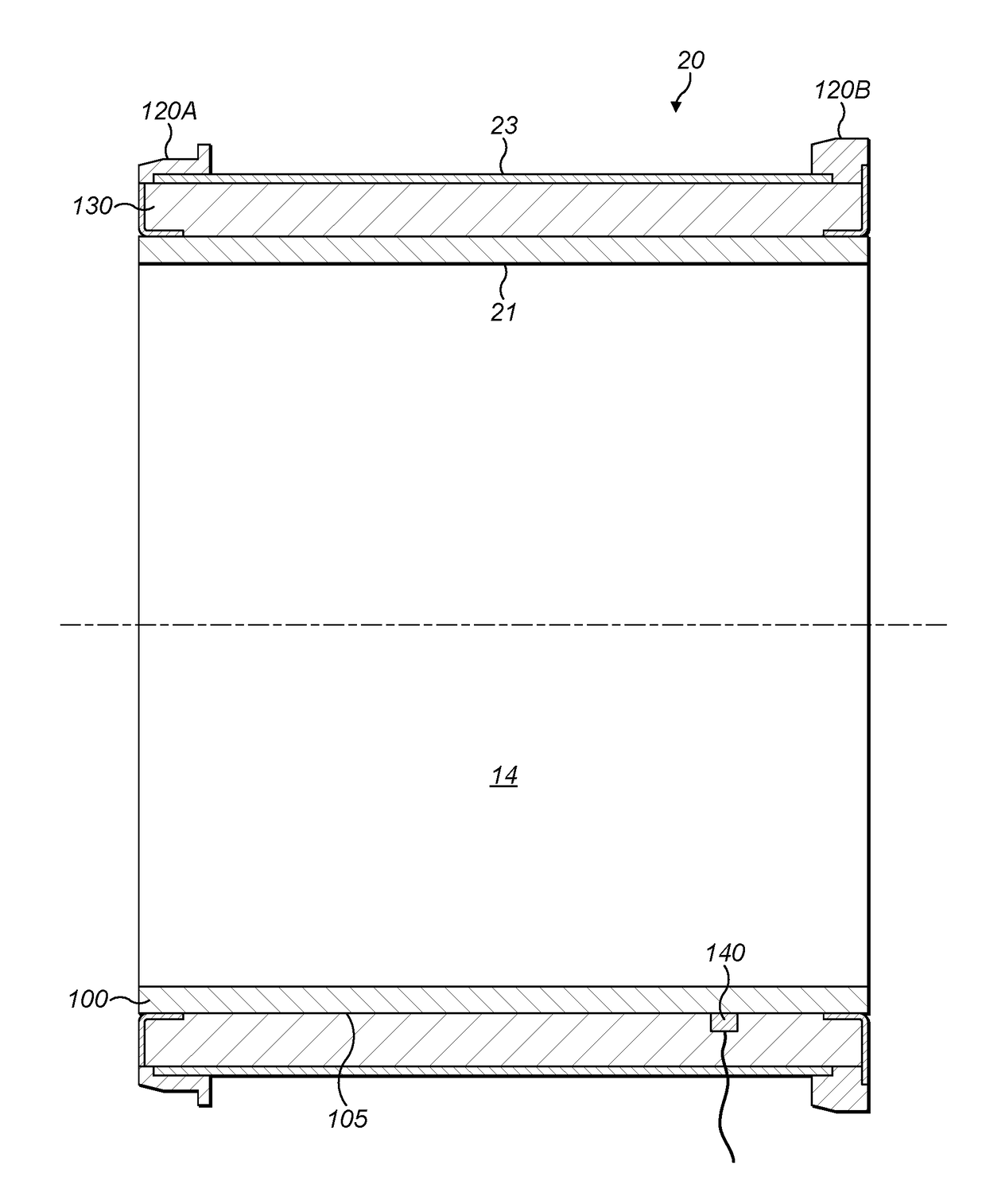
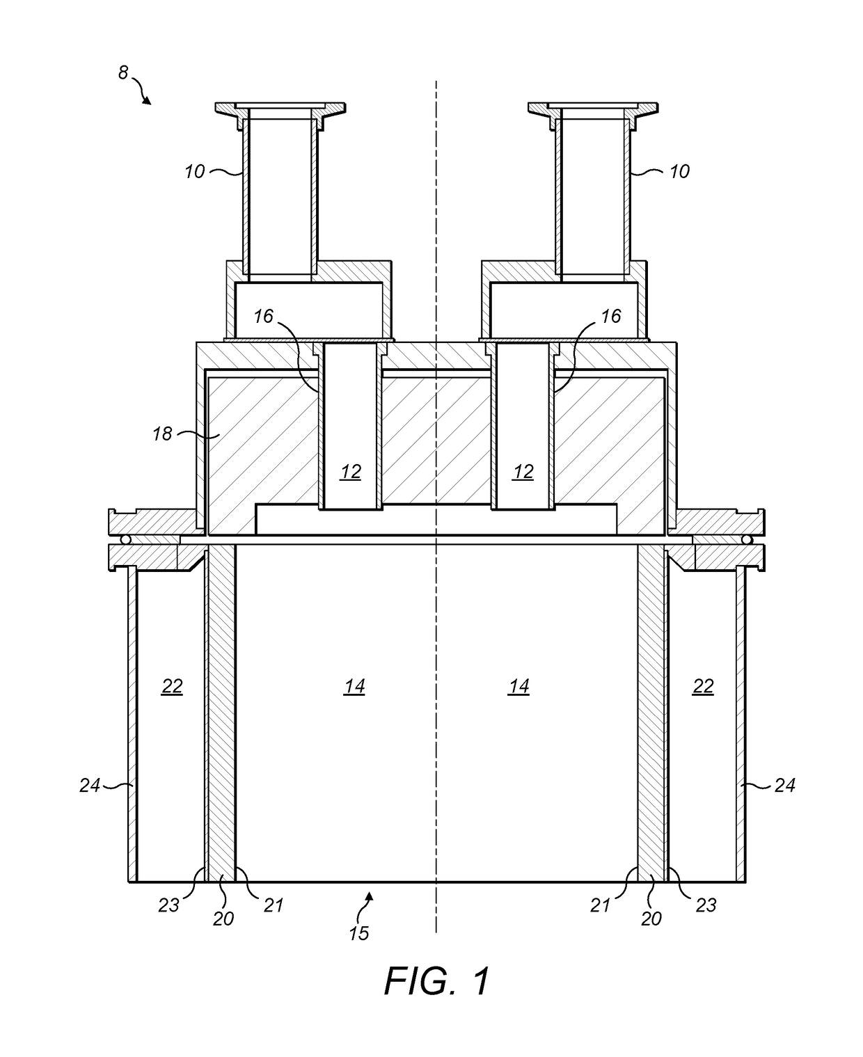
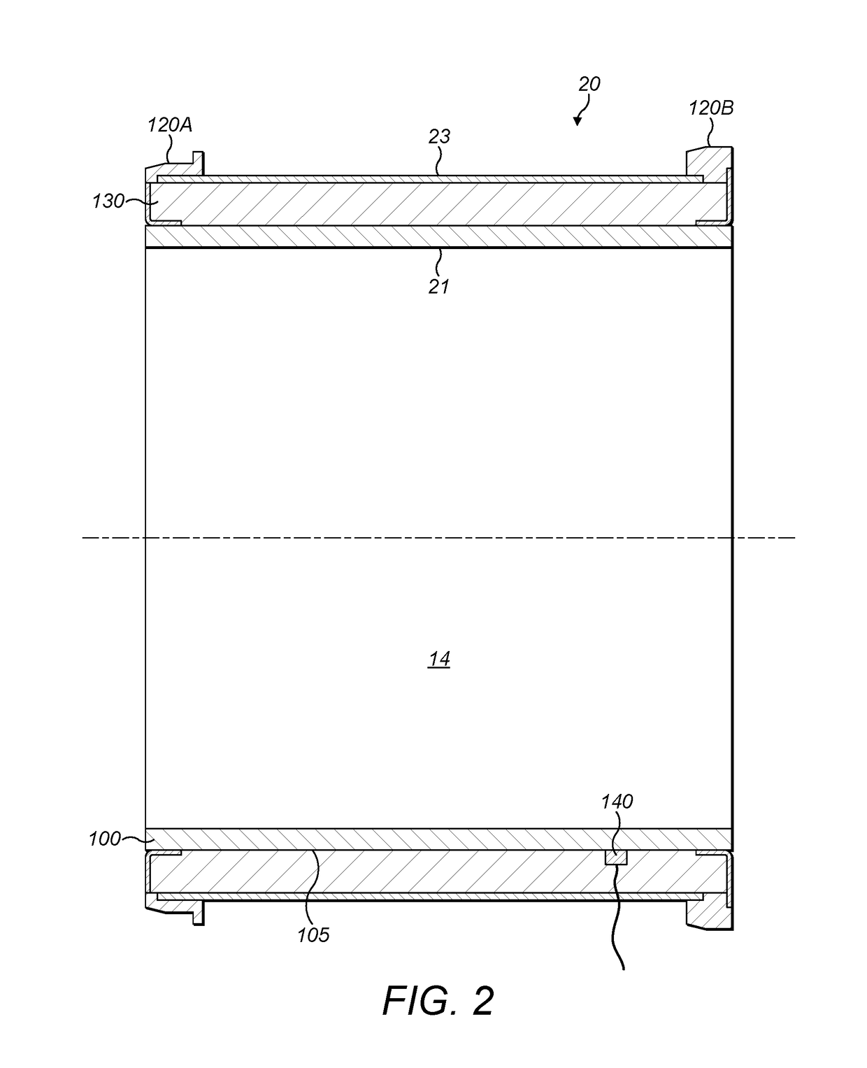
[0034]Before discussing the embodiments in any more detail, first an overview will be provided. Embodiments provide a radiant burner which is particularly suited to operate in a so-called “green mode”, where the burner is extinguished during periods of processing tool inactivity (for example, during idle steps), these periods may be frequent and of short duration. The radiant burner liner has a sintered metal fibre sleeve which is surrounded by an insulating sleeve, which replaces a typical ceramic radiant burner liner. The combination of the sintered metal fibre sleeve and the insulating sleeve provides a radiant burner which operates under almost identical conditions and with improved efficiency compared with existing radiant burners, but which is able to resist shocks due to thermal cycling. Also, in order to improve the warm-up time of the radiant burner from cold, the mix of the combustion materials may be adjusted to make the mixture rich before reverting to lean conditions du...


PUM


Abstract

A radiant burner and method are disclosed. The radiant burner is for treating an effluent gas stream from a manufacturing process tool, the radiant burner comprises: a sintered metal fibre sleeve through which combustion materials pass for combustion proximate to an inner combustion surface of the sintered metal fibre sleeve; and an insulating sleeve surrounding the sintered metal to fibre sleeve and through which the combustion materials pass. In this way, a radiant burner is provided which does not crack due to rapid cycling caused by frequent idle steps during which the burner is extinguished. Also, by providing an insulating sleeve, the temperature within the radiant burner and the temperature of an outer surface of the radiant burner remain comparable with existing ceramic burners. This enables the radiant burner to be substituted in place of existing ceramic burners as a line-replaceable unit which does not suffer from cracking during such frequent and short-duration periods of process tool inactivity.

Description

[0001]This application is a national stage entry under 35 U.S.C. §371 of International Application No. PCT / GB2015 / 053287, filed Nov. 2, 2015, which application claims priority from United Kingdom Application No. GB 1421131.2, filed Nov. 28, 2014, the entire content of which is incorporated herein by reference.TECHNICAL FIELD OF THE INVENTION[0002]The present invention relates to a radiant burner and method.BACKGROUND OF THE INVENTION[0003]Radiant burners are known and are typically used for treating an effluent gas stream from a manufacturing processing tool used in, for example, the semiconductor or flat panel display manufacturing industry. During such manufacturing, residual perfluorinated compounds (PFCs) and other compounds exist in the effluent gas stream pumped from the process tool. PFCs are difficult to remove from the effluent gas and their release into the environment is undesirable because they are known to have relatively high greenhouse activity.[0004]Known radiant bur...

Claims


Application Information

Patent Timeline
IPC IPC(8): F23G7/06F23D14/14F23N1/02
CPCF23G7/065F23D14/145F23N2025/16F23D2212/103F23G2207/101F23N1/02F23N1/022F23N5/022F23G2209/142F23G2900/50007F23D2203/1012F23D2203/1055F23D2203/106F23D2212/201F23N2225/16F23N2237/08F23D14/16
Inventor SEELEY, ANDREW JAMES
Owner EDWARDS LTD
Why Eureka
Try Eureka