Linear post-regulator

Active Publication Date: 2017-11-09
SIGNIFY HOLDING B V
View PDF8 Cites 4 Cited by
  • Summary
  • Abstract
  • Description
  • Claims
  • Application Information

AI Technical Summary

Benefits of technology

[0018]In an alternative preferred embodiment of the invention, the level of flicker on the light output of the LED lighting load is controlled on the basis of a feedback signal from a control loop of the control loop cascade. In such an embodiment, the performance parameter comprises a reference current ripple that represents a “desired current ripple” or “desired flicker”, and the control loop cascade is realized to prov

Problems solved by technology

However, this can lead to a high LED ripple current.
The ripple current might be compensated to some extent by a storage capacitor connected in parallel to the LEDs, but cannot be corrected entirely due to the limited dynamic resistance of the LEDs.
Due to the increasingly efficient LED technology, that dynamic resistance also tends to decrease further in time.
The pronounced ripple current can also adversely affect the luminous efficiency of the LEDs.
Existing linear post-regulators can be relatively inexpensive, but are generally associated with an increase in losses.
To cope with the resulting heat, additional or larger heat sinks are required, adding to the overall cost of a lighting application.
Another disadvantage of the known types of linear post-regulator is that the level of flicker on the light output can increase, since the storage capacitor

Method used


Image

  • Linear post-regulator
  • Linear post-regulator
  • Linear post-regulator

Examples


Example

[0033]In the drawings, like numbers refer to like objects throughout. Objects in the diagrams are not necessarily drawn to scale.

DETAILED DESCRIPTION OF THE EMBODIMENTS

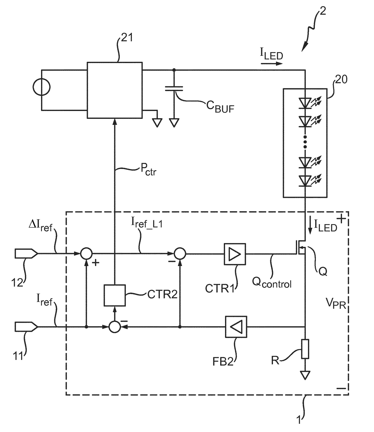
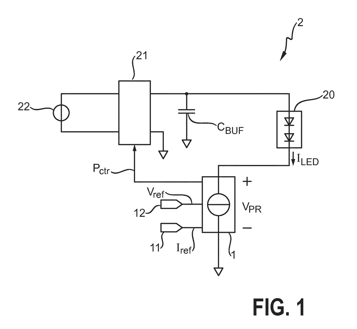
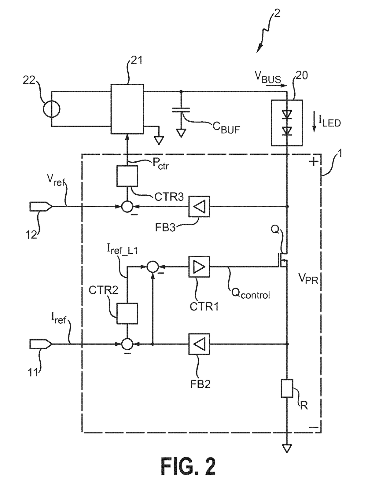
[0034]FIG. 1 shows a simplified schematic representation of an LED lighting arrangement 2 according to the invention. A power supply 22 delivers a rectified signal to a single-stage high power-factor (HPF) front-end switched-mode converter 21. A storage capacitor or buffer capacitor CBUF is connected across the outputs of the converter 21 and is arranged in parallel with a series arrangement comprising a lighting load 20 and a post-regulator 1 according to the invention. The post-regulator 1 according to the invention is realised for connection between a terminal cathode of the LED lighting load 20, and a terminal of the converter 21. The voltage VPR across the post-regulator 1 is indicated. The lighting load comprises an LED arrangement 20 as described above. The LED lighting arrangement 2 comprises the linear post-r...


PUM


Abstract

The invention describes a linear post-regulator (1) realized for use in an LED lighting arrangement (2), which linear post-regulator (1) comprises a control loop cascade (L1, L2, L3) realized for connection between a terminal of an LED lighting load (20) and a power converter (21) of the LED lighting arrangement (2); a transistor (Q) realized to regulate an LED current (ILED) through the LED lighting load (20); a first input (11) for connection to a reference current input (Iref); a second input (12) for connection to a performance parameter input (Vref, Δlref); and an output for connecting a power control output (Pctr) of the linear post-regulator (1) to the power converter (21); wherein the control loop cascade (L1, L2, L3) comprises at least two interconnected control loops (L1, L2, L3) to regulate the LED current (ILED) on the basis of the reference current input (Iref) and to regulate a further performance parameter of the LED lighting arrangement (2) on the basis of the performance parameter input (Vref, Δlref). The invention also describes an LED lighting arrangement (2), and a method of post-regulating the current of an LED lighting load (20) of an LED lighting arrangement (2).

Description

FIELD OF THE INVENTION[0001]The invention describes a linear post-regulator, an LED lighting arrangement, and a method of post-regulating the current of an LED lighting load of an LED lighting arrangement.BACKGROUND OF THE INVENTION[0002]LED lighting is becoming more and more popular as manufacturing costs are reduced to offer affordable LED lamps for many fixture types. In one widespread type of LED lighting device for indoor or outdoor lighting, a rectifier is used to rectify a mains input, and an LED driver delivers the desired voltage and current levels to an LED arrangement comprising one or more strings of LEDs. For cost reasons, many LED drivers use a single-stage power conversion architecture, even if the driver requires a high power factor. However, this can lead to a high LED ripple current. The ripple current might be compensated to some extent by a storage capacitor connected in parallel to the LEDs, but cannot be corrected entirely due to the limited dynamic resistance ...

Claims


Application Information

Patent Timeline
IPC IPC(8): H05B33/08H05B37/02H05B44/00
CPCH05B33/0812H05B33/0848H05B37/0272H05B45/395H05B45/375H05B47/19Y02B20/30H05B45/14
Inventor ELFERICH, REINHOLD
Owner SIGNIFY HOLDING B V
Why Eureka
Try Eureka