Reforming process with improved heater integration

a technology of integrating and forming process, applied in the direction of thermal naphtha reforming, thermal non-catalytic cracking, hydrocarbon oil treatment, etc., can solve the problems of conventional designs suffering disadvantages, high cost of fuel, and u-tube fired heater assembly

Active Publication Date: 2017-11-16
UOP LLC
View PDF4 Cites 1 Cited by
  • Summary
  • Abstract
  • Description
  • Claims
  • Application Information

AI Technical Summary

Problems solved by technology

The U-tube fired heater assembly is an expensive mainstay of catalytic reforming.
However, in view of the rising costs of fuel, conventional designs suffer disadvantages.
Specifically, the production of steam by convective sections is non-optimal as steam is provided in other areas of hydrocarbon processing plants.
However, this process does not permit effective temperature control for the charge heater discharge temperature, resulting in under-utilization of first reactor process yield.

Method used


Image

  • Reforming process with improved heater integration
  • Reforming process with improved heater integration
  • Reforming process with improved heater integration

Examples


specific embodiments

[0056]While the following is described in conjunction with specific embodiments, it will be understood that this description is intended to illustrate and not limit the scope of the preceding description and the appended claims.

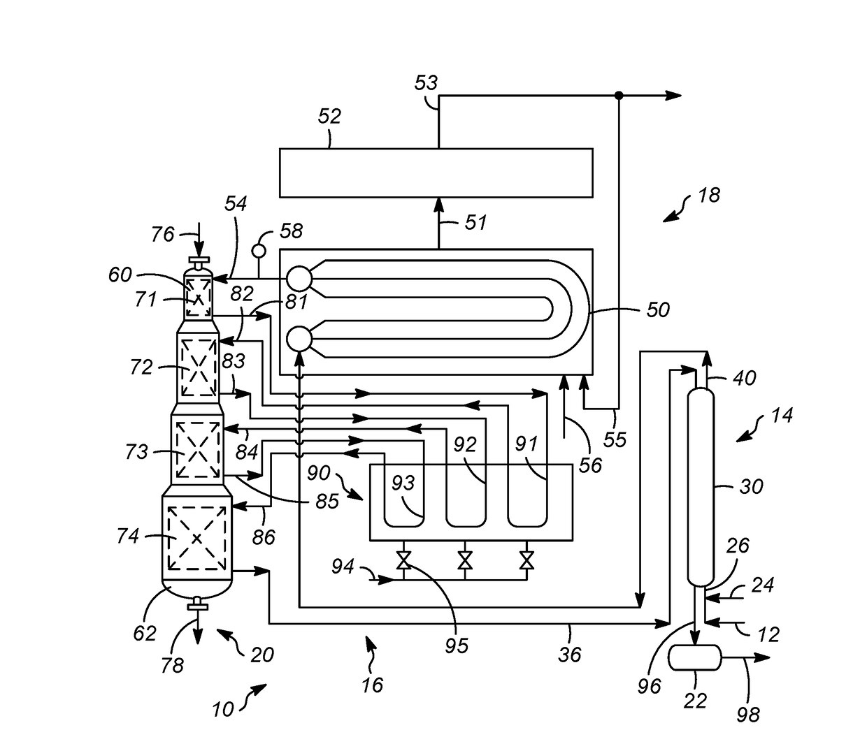
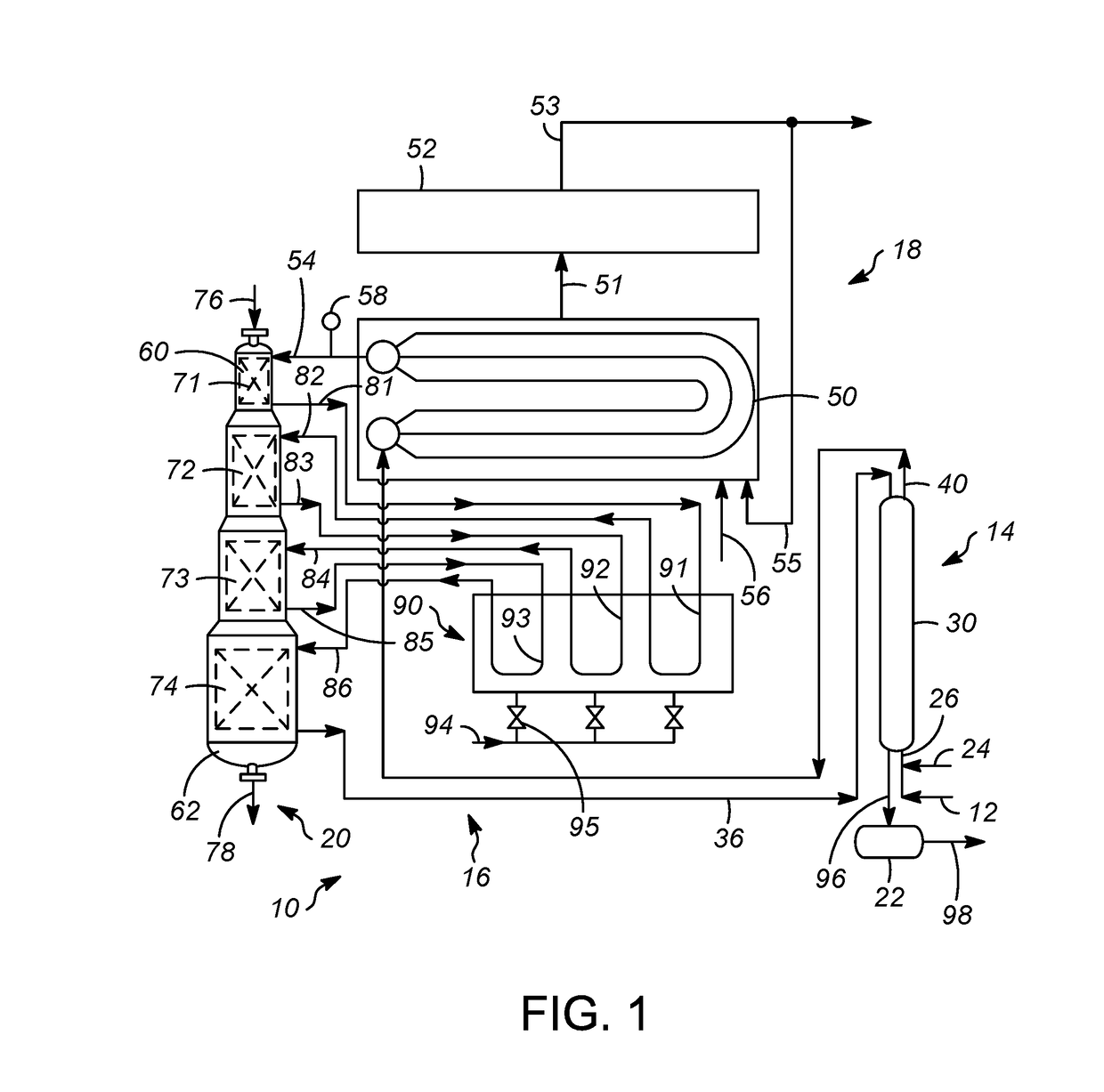
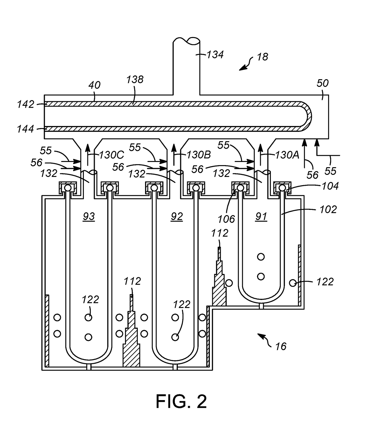
[0057]A first embodiment of the invention is a method for processing a hydrocarbon stream, the method comprising heating a feed stream in a convective bank; reacting the heated feed stream in a first reaction zone to form a first effluent; heating the first effluent in a first radiant cell, wherein the first radiant cell combusts fuel to heat the first effluent and forms a first exhaust gas; contacting the first exhaust gas with the convective bank to heat the feed stream; and controlling an outlet temperature of the heated feed stream from the convective bank by introducing an additional gas stream into the convective bank. An embodiment of the invention is one, any or all of prior embodiments in this paragraph up through the first embodiment in this paragra...


PUM

PropertyMeasurementUnit
temperatureaaaaaaaaaa
boiling pointaaaaaaaaaa

Abstract

A method and apparatus for processing a hydrocarbon stream are described. The method includes heating a feed stream in a convective bank. The heated feed stream is reacted in a first reaction zone to form a first effluent, which is heated in a first radiant cell. The first radiant cell combusts fuel to heat the first effluent and forms a first exhaust gas. The first exhaust gas is contacted with the convective bank to heat the feed stream. The outlet temperature the heated feed stream from the convective bank is controlled by introducing an additional gas stream into the convective bank. There can be additional reaction zones and radiant heaters.

Description

CROSS-REFERENCE TO RELATED APPLICATION[0001]This application claims priority from Provisional Application No. 62 / 336,349 filed May 13, 2016, the contents of which cited application are hereby incorporated by reference in its entirety.BACKGROUND OF THE INVENTION[0002]Hydrocarbon conversion processes often employ a series of reaction zones through which hydrocarbons pass. Each reaction zone may have its own unique process requirements, including a required temperature. Accordingly, each reaction zone requires a sufficient amount of heating upstream of the reaction zone to achieve the required temperature for performing the desired hydrocarbon conversion therein.[0003]One well-known hydrocarbon conversion process is catalytic reforming. Catalytic reforming is a well-established hydrocarbon conversion process employed in the petroleum refining industry for improving the octane quality of hydrocarbon feed streams. The primary product of catalytic reforming is a gasoline blending componen...

Claims


Application Information

Patent Timeline
Patent Type & Authority Applications(United States)
IPC IPC(8): C10G69/08C10G69/00
CPCC10G69/08C10G69/00C10G2300/4006C10G35/02C10G35/24C10G59/02C10G9/36
Inventor EGOLF, BRYAN J.BRABSON, CHARLESHARTMAN, WILLIAM M.YANEZ, WILLIAMMARTIN, MATTHEWLOK, KA
Owner UOP LLC
Why Eureka
Try Eureka