Assay systems for point of care detection of ocular analytes

Inactive Publication Date: 2017-11-16
INSIGHT INSTR
4 Cites 12 Cited by

AI-Extracted Technical Summary

Problems solved by technology

However, the treatment regimens with these anti-VEGF or anti cytokine drugs consist of intravitreal injections at fixed (frequently monthly) intervals for sometimes unlimited duration at great financial cost to the patient and adverse effects on the patient's quali...

Method used

[0054]Embodiments of the invention relate to the quick and accurate determination of certain biomarkers in fluid, gel, or tissue samples from a subject, preferably samples taken from or associated with the eye. Rapid clinical monitoring of important biomarkers of disease, for example inflammatory or pro-angiogenic factors in patients with vitreoretinal disease, is useful to prevent unnecessary repeat treatments (such as intravitreal injections) for patients and to reduce cost for both patients and health care providers.
[0056]In general, an analyte detection device for determining the presence or amount of an analyte in a sample includes a sample staging chamber and a test chamber. The test chamber usually includes components and reagents that specifically interact with the analyte, for example a capture molecule that can specifically bind the target analyte to be detected or quantitated. In a specific embodiment, the sample staging chamber is in fluid communication with an aspirator and an aspiration conduit that delivers sample to the analyte detection device. The analyte detection device may also include a valve positioned between the sample staging chamber and the test chamber to facilitate creation of a vacuum during delivery of the sample to the sample chamber, and which subsequently allows the transfer of sample from sample chamber to the test chamber. Typically, the valve is a manual valve or one-way valve that is closed during aspiration.
[0076]It has been discovered that a certain threshold level of analyte must be detected in a sample in order to provide beneficial information regarding disease state. Through significant trial and error experimentation, optimal concentrations of the conjugate antibody and coating antibody in order to properly detect the analyte, while avoiding false positives, have been determined. This information is provided below.
[0078]The capture molecule or capture antibody (also referred to herein as the membrane capture molecule, membrane antibody, coating molecule or coating antibody in the context of LFIA) is a capture molecule that is immobilized to the assay platform at a certain location, preferably on or in a test line. To avoid interference with the binding to the analyte, the conjugate reagent is a conjugate antibody (or other specific binding molecule) and recognizes a different epitope than the capture molecule recognizes. In certain embodiments, the conjugate binding molecule typically is a monoclonal antibody or binding fragment thereof which is has highly specific binding (avidity and affinity) for the target analyte. The test reagent typically is an antibody (either polyclonal or monoclonal) or aptamer, or any specific binding partner that binds to the target.
[0093]SELEX (a method for in vitro evolution of nucleic acids for the desired binding characteristics) involves preparing a large number of (usually randomized) candidate nucleic acids and binding a mixture of these candidates to the desired target, washing to remove unbound material, separating the bound nucleic acids, and isolating and identifying the bound sequences. These purified individual sequences are the aptamers. Usually, several rounds of selection are performed to refine and improve the affinity of the selected aptamer, usually alternating with rounds of amplification of the sequences. Thus, starting with a randomized mixture, repeated cycles of contacting with the target under binding conditions, purifying bound sequences and amplifying the bound sequences, SELEX results in a ligand-enriched mixture of nucleic acids which can be repeated as many times as needed to yield a highly specific, strong-binding nucleic acid aptamer. This process is described in more detail in U.S. Pat. Nos. 5,475,096, 5,580,737, 5,567,588, 5,705,337, 5,707,796, 5,763,177, 6,011,577, and 6,699,843. Another screening method to identify aptamers is described in U.S. Pat. No. 5,270,163. Any of the methods described in these patents can be used to produce aptamers suitable for this invention.
[0098]Because peptide aptamers are small, simple peptides with a single variable loop region tied to a protein at both ends, the peptide aptamer tertiary structures are constrained by the protein scaffold to which they are attached, reducing flexibility and often therefore effectiveness. This structural constraint also, however, can greatly increase the binding affinity of a peptide aptamer to levels comparable to an antibody's (nanomolar) range.
[0101]Aptamers can be modified, for example by combination with a ribozyme to self-cleave in the presence of their target molecule. Additional possible modifications include replacing the 2′ position of nucleotides with a fluoroamino or O-methyl group for enhanced nuclease resistance. A second addition in the form of a “mini hairpin DNA” can impart a more compact and stable structure that resists enzymatic digestion and extends its life in solution. Bridging phosphorothioates also can be added, as well as end caps to reverse polarity of the chain and linker sequences (e.g., PEG) for ease in conjugation. Adding an unnatural or modified base to a standard aptamer can increase its ability bind to target molecules as well. Further, “secondary aptamers” also are contemplated for use with the invention in certain embodiments. Secondary aptamers are designed to contain a consensus sequence derived from comparing two or more known aptamers to a given target.
[0104]Affimers are easy to express at high yields using bacterial, mammalian, insect or any convenient cells. General methods are as follows: A phage display library of about 1010 randomized potential target-binding sequences is generated and screened to identify a sequence with the desired high affinity and specific binding. Multiple rounds of screening, purification and i...

Benefits of technology

[0007]Embodiments of the invention provided herein enable quick detection and monitoring of biomarker levels in a biological sample. These tests can determine whether treatment should be given or to determine the efficacy of the treatment. With this information, unnecessary treatment rates and unnecessary repeat intravitreal injections can be avoided, red...

Abstract

Disclosed herein are systems and methods for detecting ocular analytes in vitreous humor or aqueous humor. Specifically exemplified are systems having a sample acquisition device that is inline with an analyte detection device. The system embodiments allow for the easy procurement and testing of samples. In a typical embodiment, the analyte detection device includes a sample staging chamber and a test chamber that comprises reagents that specifically interact with the analyte. The test chamber may include a sample pad, a conjugate pad having at least one conjugate reagent specific to the analyte loaded thereon, an assay platform having a substrate with at least one test region having a test reagent immobilized thereon, the test reagent being specific to the analyte; and an optional absorbent pad.

Application Domain

Technology Topic

Point of careAbsorbent Pads +6

Image

  • Assay systems for point of care detection of ocular analytes
  • Assay systems for point of care detection of ocular analytes
  • Assay systems for point of care detection of ocular analytes

Examples

  • Experimental program(3)

Example

Example 1. Lateral Flow Immunoassay (LFIA), Antibody Capture
[0116]FIG. 7 shows a depiction of a typical LFIA arrangement. Sample is loaded onto a sample pad 29, which is in operable contact with a conjugate pad 31 that is loaded with conjugate antibody. A liquid, analyte-containing sample disposed on the sample pad traverses from the sample pad to the conjugate pad where the conjugate antibody binds to analyte in the sample. The analyte-containing sample (now with analyte/conjugate antibody complex) moves from the conjugate pad to the assay platform 33. The assay platform 33 typically includes at least one test region 35 having a test reagent immobilized thereon, the test reagent being specific to the analyte. As analyte-containing sample traverses across the assay platform, analyte of the analyte/conjugate antibody complex binds to the test reagent. The assay platform also includes a control region which has an antibody that is directed to conjugate antibody. This assists in determining whether the assay developed properly, and/or assists in calibrating the signal of the test region(s). The LFIA may also include an absorbent pad 37, which helps drive the flow of analyte containing sample via capillary action.
[0117]In the context of lateral flow immunoassay devices, these are typically constructed of a solid support that provides lateral flow of a sample through the assay platform when a sample is applied to a sample pad that is in operable contact with the assay platform. The sample pad and the assay platform are typically constructed of a material such as nitrocellulose, glass fiber, paper, nylon, or a synthetic nanoporous polymer. Suitable materials are well known in the art and are described, for example, in U.S. Pat. No. 7,256,053 to Hu, U.S. Pat. No. 7,214,417 to Lee et al., U.S. Pat. No. 7,238,538 to Freitag et al., U.S. Pat. No. 7,238,322 to Wang et al., U.S. Pat. No. 7,229,839 to Thayer et al., U.S. Pat. No. 7,226,793 to Jerome et al., RE39,664 to Gordon et al., U.S. Pat. No. 7,205,159 to Cole et al., U.S. Pat. No. 7,189,522 to Esfandiari, U.S. Pat. No. 7,186,566 to Qian, U.S. Pat. No. 7,166,208 to Zweig, U.S. Pat. No. 7,144,742 to Boehringer et al., U.S. Pat. No. 7,132,078 to Rawson et al., U.S. Pat. No. 7,097,983 to Markovsky et al., U.S. Pat. No. 7,090,803 to Gould et al., U.S. Pat. No. 7,045,342 to Nazareth et al., U.S. Pat. No. 7,030,210 to Cleaver et al., U.S. Pat. No. 6,981,522 to O'Connor et al., U.S. Pat. No. 6,924,153 to Boehringer et al., U.S. Pat. No. 6,849,414 to Guan et al., U.S. Pat. No. 6,844,200 to Brock, U.S. Pat. No. 6,841,159 to Simonson, U.S. Pat. No. 6,767,714 to Nazareth et al., U.S. Pat. No. 6,699,722 to Bauer et al., U.S. Pat. No. 6,656,744 to Pronovost et al., U.S. Pat. No. 6,528,323 to Thayer et al., U.S. Pat. No. 6,297,020 to Brock, U.S. Pat. No. 6,140,134 to Rittenburg, U.S. Pat. No. 6,136,610 to Polito et al., U.S. Pat. No. 5,965,458 to Kouvonen et al., U.S. Pat. No. 5,712,170 to Kouvanen et al., U.S. Pat. No. 4,956,302 to Gordon et al., and U.S. Pat. No. 4,943,522 to Eisinger et al., all of which are incorporated herein by this reference. The use of such devices for the performance of sandwich immunoassays is also well known in the art, and is described, for example, in U.S. Pat. No. 7,141,436 to Gatto-Menking et al. and U.S. Pat. No. 6,017,767 to Chandler, U.S. Pat. No. 6,372,516 to Ming Sun, all of which are incorporated herein by this reference.
[0118]As indicated above, an analyte-containing sample traverses the assay platform by way of capillary action. As the sample moves across the assay platform analytes in the sample encounter different biomolecules, such as antibodies, that bind to the analyte. Materials from which the assay platform can be made typically include, but are not limited to, nitrocellulose, glass fiber, paper, nylon, or a synthetic nanoporous polymer.
[0119]LFA reproducibility is not only influenced by design and manufacturing, but also by the components used in the assembly of the test. The assay platform membrane has a significant impact on the performance of the test results. Nitrocellulose membranes are manufactured by dissolving the raw materials in a mixture of organic solvents and water, pouring this casting mix onto a solid belt-like support, and evaporating the solvents under controlled conditions of temperature, humidity, and belt speed within the membrane manufacturing machine.
[0120]Using new membrane formulations and improved manufacturing conditions various variables of the membrane can be controlled according to techniques known in the art. Such variables include:
[0121]i. Flow Rate of Membrane This is determined empirically, and will vary according to the viscosity of the sample used. Data for the flow rates of specific membranes with specific sample types are supplied by the manufacturer.
[0122]ii. Membrane Porosity This describes the fraction of the membrane that is air (e.g., a membrane with a porosity of 0.7 is 70% air), and will have an impact on the flow rate of the membrane.
[0123]iii. Membrane Capacity By definition, this is the amount of volume of sample that a given membrane can hold, and is determined as a factor of the length (L), width (W), thickness (T), and porosity (P) of the membrane: L×W×T×P=Membrane Capacity. A second important calculation is the determination of the amount of antibody that can be bound per unit area of membrane (pertaining to the capture and control lines). This calculation involves the following variables. Dimensions of representative capture antibody line: 0.1 cm×0.8 cm=0.08 cm2. Binding capacity of membrane used for capture antibody (obtained from the membrane manufacturer).
[0124]Conjugate Pad and Reagents
[0125]In a typical embodiment, the conjugate pad comprises an absorbed but not immobilized conjugate comprising a conjugate reagent (e.g. antibody) specific for the analyte and conjugated directly to detectable marker, such as a gold nanoparticle. The conjugate reagent can be loaded onto the conjugate pad using an aqueous conjugate antibody solution. The conjugate antibody solution comprises the conjugate antibody and other components provided for solution stability, pH regulation, and the like. Examples of such ancillary components include buffers, salts, preservatives, etc. Specific examples include BSA, sucrose, trehalose, tween-20, PEG, water, HEPES, Polyvinyl pyrolidone (PVP), and the like. In an embodiment, the conjugate antibody solution is applied to the conjugate pad and allowed to dry for a period of time (e.g., 0.5, 0.7, 1, 1.5 hr) at a specified temperature (e.g., 23, 25, 30, 35, 37, 40° C.). By such application or an equivalent method, the conjugate is loaded onto the conjugate pad. In this regard, the conjugate is not immobilized on the conjugate pad, and can be carried from the conjugate pad via an assay solution, such as along a capillary flow path, into the porous membrane.
[0126]As shown in the data provided in the Examples section herein, the type of antibodies used in the assay reaction can have a dramatic impact on sensitivity as well as the accuracy of the assay (e.g. avoidance of false positives). The conjugate antibody pertains to the antibody that the sample will typically encounter first while passing along the assay platform. The conjugate antibody specifically binds to an analyte of interest in the sample. In addition, the conjugate antibody typically comprises a label associated therewith.

Example

Example 2. Lateral Flow Immunoassay (LFIA), Aptamer Capture
[0127]Example 1 is repeated using aptamers in place of one or more of the antibody reagents.

Example

Example 3. Description of Illustrated Embodiments
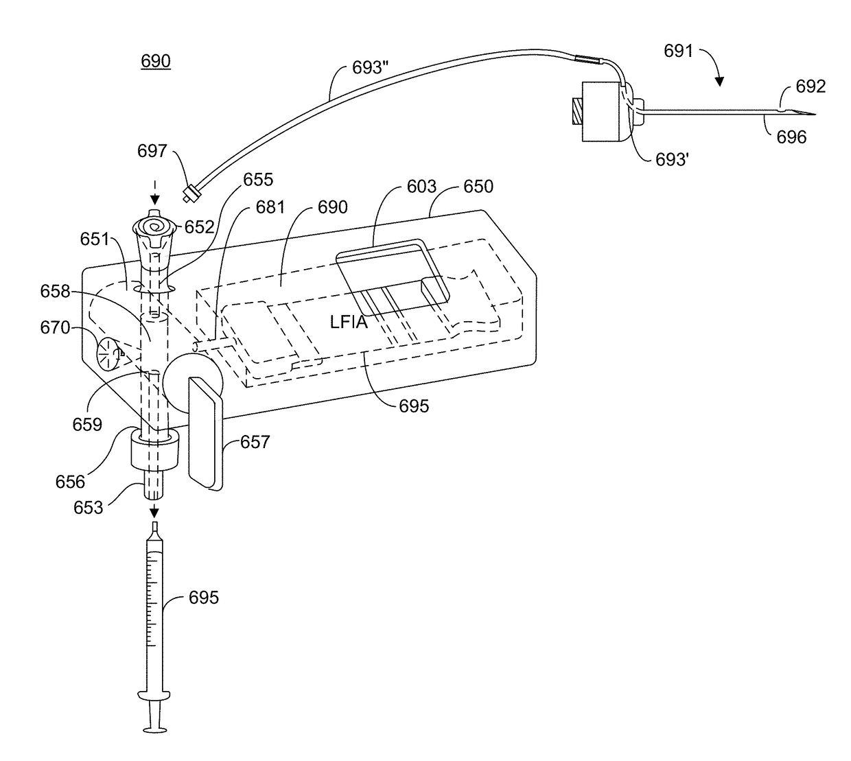
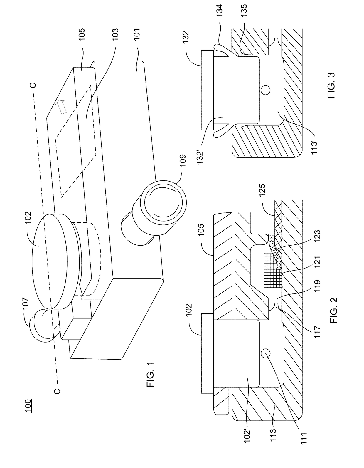
[0128]FIG. 1 shows a side perspective view of an analyte detection device 100 that receives a sample and determining the presence or amount of an analyte in the sample. The device 100 has an outer housing 101 and an inlet 107 into which a sample is delivered to the device as well as an outlet 109 to which an aspirator or other component can be connected. A sample acquisition device (such as 691 shown in FIG. 8 and described herein) can be connected to the inlet 107 and an aspirator (such as 695 shown in FIG. 8 and described herein) can be connected to 109 for purposes of delivering sample to the device 100. The device 100 includes a sample actuator 102 that serves to drive sample into internal components of the device 100. To prevent accidental actuation of the actuator 102, as well as movement of the actuator during the sample aspiration phase, a safety tab 105 overlays the top surface device but underneath a lip of the actuator 102. Shown underneath the safety tab 105 is a window 103 which allows visualization of certain components within the housing.
[0129]FIG. 2 shows a partial cross-section of device 100 along axis C-C. Safety tab 105 can be seen adjacent to the sample actuator 102. Within housing 101, a sample staging chamber 113 is provided having a portal 111 that is in fluid communication with inlet 107. The device also has a test chamber 119 that is in fluid communication with the sample staging chamber 113. A one-way valve 117 is positioned in between the sample staging chamber 113 and test chamber 119. Within the test chamber is a sample pad 121 in operable contact with a conjugate pad 123, which is in operable contact with an assay platform 125. The test chamber can be separated into different portions by a divider 124. The divider 124 helps prevent spillage of sample onto the assay platform thereby limiting movement of sample to capillary action. A sample is delivered to the sample staging chamber 113 and then pushed into the test chamber by depressing the actuator 102 (with safety tab 105 removed), which drives the lower body portion 102′ of the actuator 102 into the sample staging chamber 113.
[0130]FIG. 3 shows an alternative example of a sample staging chamber 113′ and an actuator 132. The actuator 132 includes flap portion(s) 134 which hold back the actuator 132 during sample aspiration and to prevent accidental actuation. When a threshold force is applied to actuator 132, the actuator drops downward. The walls into which the lower portion 132′ of the actuator sits may have receiving notches 135 into which the flap portion can rest upon actuation.
[0131]FIGS. 4A and 4B pertain to an analyte device embodiment 250. FIG. 4A represents a top, partial cross-section view that shows the interaction of sample actuator 351 that possesses a cut-away to form the sample staging chamber 213. The sample actuator 351 (see also FIG. 5C) has a channel 355 defined therein to allow sample to flow from the inlet 307 to the sample staging chamber 213. A sample acquisition device (such as 691 shown in FIG. 8 and described herein) can be connected to the inlet 307 and an aspirator (such as 695 shown in FIG. 8 and described herein) can be connected to proximally relative to channel 355 for purposes of delivering sample to the device 100. The device 250 also includes a test chamber 219 into which a test device, such as an LFIA, can be situated. A one-way valve 251 is positioned between the sample staging chamber 213 and the test chamber 219. FIG. 4B shows a partial, side longitudinal cross section along axis D-D from FIG. 4A. As shown, analyte containing sample present in the sample staging chamber 213 is transferred to the test chamber 219 in response to the rotation of the sample actuator 351 by application of force to actuator tab 357. Sample flows through valve 251 and into test chamber 219 where the fluid contacts sample pad 221. The rotation of the sample actuator serves to close the channel 355 to prevent backflow of the sample. Sample pad 221 is in operable contact with conjugate pad 223, which is in operable contact with assay platform 225. The sample staging chamber 213 is formed by the cutaway area and wedge portion 359 of the sample actuator 351 that interacts with the shelf portion 233 associated with the device housing. As the sample actuator rotates 351 the sample staging chamber 213 collapses which pushes fluid through valve 251.
[0132]FIG. 5A shows a partial side cross-section view of an analyte device embodiment 350 similar to embodiment 250 but includes a manual valve 340 that controls fluid from the sample staging chamber 313 to the test chamber 319 in place of the one-way valve 251. The manual valve 340 has passage 343 that will allow fluid in the sample staging chamber 313 to flow into the test chamber 319 when turned such as shown in FIG. 5B. The sample actuator 351 shown in FIG. 5C is the same as that shown in FIG. 4A, and is also similarly arranged such that the cutaway and wedge 359 align with shelf portion 333 to form the sample staging chamber 313. The sample actuator 351 also has a channel 355 that is in fluid communication with the sample staging chamber 313. With the valve 340 in a closed position and sample actuator 351 in fully open position as shown in FIG. 4A, sample is drawn into the sample staging chamber 313. The test chamber 319 includes a sample pad 321, conjugate pad 323 and assay platform 325. Turning to FIG. 5B, the valve 340 is opened so that the passage 343 allows the sample to flow from staging chamber to the test chamber. In conjunction with this, the actuator 351 is rotated via force to actuator tab 357, which pushes the sample through valve 340 as the wedge 359 approaches the shelf 333.
[0133]FIGS. 6A and 6B show an alternative arrangement of an analyte device 650 which receives sample from a top to bottom, or bottom to top, direction, as opposed to side to side. The sample actuator 651 has a sample staging chamber 613 that is in fluid communication with an inlet 607 via conduit portion 655 and aperture 658. In the sample receiving position, as shown in FIG. 6A, sample is delivered through inlet 607 and travels to the sample staging chamber 613. Sample is typically drawn through by aspiration applied to aspiration outlet 609 that applies a vacuum to the sample staging chamber 613 through portal 659 and conduit portion 656. In the position of the sample actuator 651 shown in FIG. 6A, the aperture 670 and test chamber conduit 681 are closed off from the sample staging chamber 613. The device further includes a test device 695 (e.g. LFIA) positioned in the test chamber 619 and a window 603 that allows visualization of at least a portion of the test device 695.
[0134]In FIG. 6B, the sample actuator 651 is rotated by turning actuator tab 657 which causes the sample chamber 613 to align so that the portal 659 aligns with aperture 670 to allow passage of air to staging chamber 613 and portal 658 aligns with the test conduit 681 to allow sample to flow to the test chamber 619.
[0135]Turning to FIG. 8, shown is a system arrangement 690 a sample acquisition device (probe) 691 that comprises a cannulated needle member 696 having an aspiration inlet 692 in fluid communication with a first aspiration conduit portion 693′. The sample acquisition device 691, can be associated with a vitrectomy device (e.g. element 12 shown in FIG. 11). The first aspiration conduit portion 693′ is in fluid communication with a second aspiration conduit portion 693″. The proximal end of the second aspiration conduit portion 693″ comprises a connector 697 that engages to the distal end 652 of conduit portion 655. Also shown is an aspirator (e.g. syringe) 695 which engages to the proximal end 653 of the conduit portion 656. When engaged, the aspiration inlet 692, aspiration conduit portions 693′,693″, conduit portion 655, conduit portion 656 and aspirator 695 are all in fluid communication, and the aspiration conduit portions 693′ and 693″, conduit portion 655 and conduit portion 656 together form an aspiration conduit. The other elements shown in FIG. 8 that are not specifically discussed in this paragraph correlate to the elements discussed in relation to FIG. 6.
[0136]FIG. 9 shows another embodiment of a system arrangement 900. The system 900 includes a sample acquisition device (probe) 991 having an aspiration conduit portion 993 in fluid communication therewith. The sample acquisition device 991 can be associated with a vitrectomy device (e.g. element 12 shown in FIG. 11). The proximal end 994 of the aspiration conduit portion 993 is engageable to aspiration conduit portion 955 at its distal end 956. At the proximal end 957 of the aspiration conduit portion 955 an aspirator 995 (e.g. syringe) is engaged. Within the aspiration conduit portion 955 is a one-way valve 975. The aspiration conduit portion 955 is in fluid communication with the sample conduit 980 that leads to a test chamber 981, which is shown to contain an LFA strip. A one-way valve 976 is positioned at the sample conduit between the aspiration conduit portion 955 and test chamber 981.
[0137]During use of the system 900, in a first step 1, sample is drawn into the sample acquisition device 991 then through aspiration conduit portion 993 then through aspiration conduit portion 955. Provided on the proximal body of the aspiration conduit portion 955 are markings 985 to assist the user in determining the amount of sample that has been obtained. As vacuum is applied by the aspirator 995 causing fluid to flow through valve 975 while valve 976 is closed. Upon obtaining an appropriate amount of sample, as determined by sample reaching a desired marking 985, pressure is then applied by the aspirator 995 to push the sample back up the aspiration conduit 955. This causes valve 976 to open to allow passage of fluid and valve 975 to close resulting in fluid passing through the sample conduit 980 to the test chamber 981. Provided as an optional feature upstream of the proximal end 957 is a valve 986 (e.g. stopcock as shown), which may be included in the system 900 to assist in control of aspiration. A divider such as 124 shown in FIG. 2 can be provided to prevent undesired spillage or seepage of sample onto the assay platform.
[0138]Another embodiment 1000 is shown in FIG. 10, which pertains to a system arrangement that provides one directional flow for sample acquisition and analyte detection. Sample is drawn into the sample acquisition device (probe) 991 then through aspiration conduit portion 993 then through distal end 1056 of aspiration conduit portion 1055. The sample acquisition device 991 can be associated with a vitrectomy device (e.g. element 12 shown in FIG. 11). The aspiration conduit 1055 is in proximity to a LFA strip such that when sample is drawn to the test chamber 1081, by vacuum applied to proximal end 1057 of aspiration conduit portion 1045, it is delivered to the LFIA (e.g. onto the sample pad). Provided upstream of the proximal end 1057 is a valve 986 (e.g. stopcock as shown) to assist in control of aspiration. A divider such as 124 shown in FIG. 2 can be provided to prevent undesired spillage or seepage of sample onto the assay platform. The arrangement of 1000 does not require valves to achieve sample acquisition and delivery to LFA. It should be noted that the LFA strip could be substituted with a microfluidic device or like devices for detecting analytes in a sample.
[0139]Turning to FIG. 11, a further embodiment 10 is shown that is adapted for improved and facile extraction of a vitreous biopsy from a patient's eye 11. The embodiment includes a disposable vitrectomy probe 13, that is designed for operation with a surgical hand-piece (e.g. vitrectomy device) 12. The probe 13 is in fluid communication with an aspiration tube 14 that is connectable with a separate sampling tube 15. As shown, the aspiration tube 14 and sampling tube 15 are connected with conventional Luer lock connectors 16, but those skilled in the art will appreciate that other types of suitable connectors can be used for this purpose. Entry into the eye 11 is made with the sharp tipped vitrectomy probe 13.
[0140]The aspiration tube 14 and sampling tube 15 are in fluid communication with a syringe 18. Drawing the plunger of the syringe 18 creates a vacuum that pulls in the fluid (e.g. vitreous sample) through the aspiration tube and into the sampling tube 15. Further, the fill marks 17 assist with controlling the amount of vitreous sample extracted and are placed at a strategic location on the sampling tube 15 based on the minimum volume, as well as dead volume of the tube and cassette, as is discussed further below.
[0141]The extraction of vitreous humor is a very delicate process, and exceptional care must be exercised in controlling the amount removed. Because there is a vacuum build-up in the syringe, the implementation of the stopcock 19 provides immediate and fine control of the fluid extraction process.
[0142]After completed sample acquisition and removal of the probe 13 from the eye 11, the sampling tube 15 is disconnected from the probe at the connector 16a, and connected to the analyte detection device (e.g. lateral flow assay cassette) 21 via connection port 22 (FIG. 12, e.g. Luer lok fitting). Focusing on FIGS. 11 and 12 (note that lower figure is a cross section of the embodiment shown in the upper figure along A-A axis), once the desired amount of vitreous sample is drawn into the sampling tube 15, as designated by fill marks 17, the sample can now be expressed into the sample staging chamber 34 of the cassette 21 by depressing the syringe plunger 18a and opening the stopcock 19. To prevent sample from flowing directly into the overflow passage 32 under gravity, the sample staging chamber 34 may be shaped conically expanding, to allow surface tension a gradual fill of the sample chamber 34 from the connection port 22. Addition of an open cell foam material may also be used for that purpose. A vent 33 in fluid connection with the sample staging chamber 34 prevents build up of excessive pressure in the sample staging chamber 34 and undesired pressurized infusion of sample into the sampling pad 23. A one way valve in the overflow passage 32 or the presence of wicking material in the overflow reservoir 31 may additionally help prevent backflow of excess sample back into the sample staging chamber 34.
[0143]Once the sample is delivered to the sample staging chamber 34, sample contacts the sample pad 23 and sample is transferred by capillary action to a sample transfer chamber 38 where a portion of the sample pad 23 contacts a conjugate pad 24. The end of the sample pad 23 and conjugate pad extend into the test chamber 39 where they contact with the assay platform 27 (e.g. membrane). Disposed on the assay platform 27 are a test region 25 and a control region 26. At the distal end of the test chamber 39 is disposed a wicking pad 28 that serves to wick sample passing along the assay platform 27. As shown the wicking pad 28 contacts the assay platform 27 at one end and is disposed within a wicking chamber 40 at an opposite end. A window 30 is also provided for visualizing the assay platform 27. As shown, the sample pad 23, conjugate pad 24, assay platform 27 and wicking pad 28 are disposed upon a backing material 29,
[0144]The minimum length of the sampling tube 15 is chosen to allow the assistant to operate the aspiration syringe without interfering with the surgeon's view and manipulation of the surgical instrument 12 in the operating field. The maximum length of the tube 15 is determined by the available vacuum level created by the syringe (FIG. 13) and the resulting flow rate of the sample in the sampling tube as described by the Hagen-Poiseuille equation (see Formula 1 below), as well as allowing the assistant to monitor the amount of collected fluid in the aspiration tube 14.
Equation 1 - Poiseuille ′ s law Flow = P × Π × r 4 8 × l × n p = preassure r = radius l = distance n = viscosity Since resistance = preassure / flow , therefore Resistance = 8 × l × n Π × r 4 Formula 1
[0145]According to a specific embodiment, variables of certain dimensions components of the embodiment are provided for illustration purposes in reference to FIGS. 11 and 12. An overall length of the sample tube 15 of 8″ is assumed in the embodiment3. The internal diameter (ID) of the sampling tube 15 is fabricated to allow the required sample volume to take up a significant portion of the sampling tube length (assumption of 50%)4, with easily readable fill marks5 17, which provide visual reference to the assistant when to stop the aspiration by closing the stopcock 19. The minimum sampling tube volume must take into account the dead volume of the tube 15 and cassette, not shown. For example, a sample volume of 50 ul (min of 45 ul, max of 55 uL) can thus be achieved in this embodiment by using a 0.030″ micro-bore tubing.
[0146]The sample chamber volume is equivalent to the nominal sample requirement of 35 μl for the assay7. Any volume in excess of the nominal sample requirement is displaced through overflow passage 32 into overflow reservoir 31. The volume of the overflow reservoir is designed to accept any overflow when the sampling tube is filled to the maximum fill mark8. The superscript designations in this and the preceding paragraphs refer to the noted information in Table 1.
TABLE 1 VT Volume in Sample Tube VTmin Volume in Sample Tube @ min Fill Mark VTmax Volume in Sample Tube @ max Fill Mark 5) VTmin + 10 ul LT Length of Sample Tube 3) 8″ = 200 mm LTmin Length of Sample Tube @ min Fill Mark 4) 50% of LT LTmax Length of Sample Tube @ max Fill Mark Dt Inside Diameter of Sample Tube Vs Volume of Sample required for Assay 7) 35 ul = 35 mm3 VD Dead Volume of Tube and Cassette 6) 10 ul = 10 mm3 VR Volume of Overflow Reservoir 8)
The equations below serve to define the different parameters of Table 1. The superscript 8 in equation (3) is a cross reference to note 8 in Table 1.
[0147]Equations:
V Tmin ≥ V S + V D ( 1 ) V T = π 4 D T 2 L T ( 2 ) V R ≥ V Tmax - V S ( 3 ) 8 L Tmax / L Tmin = V Tmax / V Tmin ( 4 )
[0148]Calculations:
using ( 1 ) : V Tmin ≥ V S + V D = 35 mm 3 + 10 mm 3 = 45 mm 3 _ using 4 : L Tmin = 0.5 · 200 mm = 100 mm _ using ( 2 ) : D T = 4 V Tmin π L Tmin = 4 · 45 mm 3 π · 100 mm = .76 mm _ ( .030 ″ ) using 5 : V Tmax = V Tmin + 10 mm 3 = 45 mm 3 + 10 mm 3 = 55 mm 3 _ using ( 4 ) L Tmax = 55 mm 3 45 mm 3 · 100 mm = 122 mm _ using ( 3 ) : V R ≥ V Tmax - V S = 55 mm 3 - 35 mm 3 = 20 mm 3
[0149]It should be borne in mind that all patents, patent applications, patent publications, technical publications, scientific publications, and other references referenced herein are hereby incorporated by reference in this application in order to more fully describe the state of the art to which the present invention pertains.
[0150]It is important to an understanding of the present invention to note that all technical and scientific terms used herein, unless defined herein, are intended to have the same meaning as commonly understood by one of ordinary skill in the art. The techniques employed herein are also those that are known to one of ordinary skill in the art, unless stated otherwise. For purposes of more clearly facilitating an understanding the invention as disclosed and claimed herein, the preceding definitions are provided.
[0151]While a number of embodiments of the present invention have been shown and described herein in the present context, such embodiments are provided by way of example only, and not of limitation. Numerous variations, changes and substitutions will occur to those of skill in the art without materially departing from the invention herein. For example, the present invention need not be limited to best mode disclosed herein, since other applications can equally benefit from the teachings of the present invention. Also, in the claims, any means-plus-function and step-plus-function clauses are intended to cover the structures and acts, respectively, described herein as performing the recited function and not only structural equivalents or act equivalents, but also equivalent structures or equivalent acts, respectively. Accordingly, all such modifications are intended to be included within the scope of this invention as defined in the following claims, in accordance with relevant law as to their interpretation.
[0152]While one or more embodiments of the present invention have been shown and described herein, such embodiments are provided by way of example only. Variations, changes and substitutions may be made without departing from the invention herein. Accordingly, it is intended that the invention be limited only by the spirit and scope of the appended claims. The teachings of all references cited herein are incorporated in their entirety to the extent not inconsistent with the teachings herein.
6. References
[0153]All publications mentioned below and throughout the application are hereby incorporated by reference in their entirety. [0154] 1. Wong and Tse (Eds.) Lateral Flow Immunoassay, 2009, Humana Press, a part of Springer Science+Business Media, LLC. (Library of Congress Control Number 2008939893). [0155] 2. U.S. Pat. No. 8,011,228. [0156] 3. United States Patent Application No. 2014/0193840 A1. [0157] 4. Gervais and Delamarche, Toward one-step point-of-care immunodiagnostics using capillary-driven microfluidics and PDMS substrates. Lab Chip 9:3330, 2009. [0158] 5. Gordon and Michel. Clin. Chem. 58(4):690-698, 2012. [0159] 6. Chin et al. Lab Chip 12:2118-2134, 2012. [0160] 7. Chin et al. Nat. Med. 17:1015-1019, 2011. [0161] 8. U.S. Pat. No. 5,487,725. [0162] 9. U.S. Pat. No. 5,716,363. [0163] 10. U.S. Pat. No. 5,989,262. [0164] 11. U.S. Pat. No. 6,059,792. [0165] 12. U.S. Pat. No. 7,549,972. [0166] 13. U.S. Pat. No. 8,216,246. [0167] 14. U.S. Pat. No. 8,608,753. [0168] 15. Jones et al., Nature 321:522-525, 1986. [0169] 16. Riechmann et al., Nature 332:323-329, 1988. [0170] 17. Presta, Curr. Opin. Struct. Biol. 2:593-596, 1992. [0171] 18. Vaswani and Hamilton, Ann. Allergy, Asthma & Immunol. 1:105-115, 1998. [0172] 19. Harris, Biochem. Soc. Transactions 23:1035-1038, 1995. [0173] 20. Hurle and Gross, Curr. Opin. Biotech. 5:428-433, 1994. [0174] 21. European Patent No. 404,097. [0175] 25. International Patent Application WO 1993/01161. [0176] 26. Hudson et al., Nat. Med. 9:129-134, 2003. [0177] 27. Hollinger et al., PNAS USA 90: 6444-6448, 1993. [0178] 28. Kohler and Milstein, Nature, 256:495, 1975. [0179] 29. U.S. Pat. No. 4,816,567. [0180] 30. Mage and Lamoyi, Monoclonal Antibody Production Techniques and Applications, pages 79-97. Marcel Dekker Inc., New York, 1987. [0181] 31. Methods, Volume 38, Issue 4, April 2006, Pages 324-330, Methods for Analyzing Cytokines; Edited By Daniel G. Remick and Jill Granger, Assays for cytokines using aptamers. [0182] 32. Jo et al., VEGF-binding aptides and the inhibition of choroidal and retinal neovascularization. Biomaterials 35(9):3052-3059, 2014.

PUM

no PUM

Description & Claims & Application Information

We can also present the details of the Description, Claims and Application information to help users get a comprehensive understanding of the technical details of the patent, such as background art, summary of invention, brief description of drawings, description of embodiments, and other original content. On the other hand, users can also determine the specific scope of protection of the technology through the list of claims; as well as understand the changes in the life cycle of the technology with the presentation of the patent timeline. Login to view more.

Similar technology patents

Devices and methods for esophageal lengthening and anastomosis formation

ActiveUS20170311952A1Decrease in numberReduce cost and complicationSuture equipmentsMedical imagingDistal anastomosisLong gap esophageal atresia
Owner:MAYO FOUND FOR MEDICAL EDUCATION & RES

Classification and recommendation of technical efficacy words

  • Reduce cost and complication

Devices and methods for esophageal lengthening and anastomosis formation

ActiveUS20170311952A1Decrease in numberReduce cost and complicationSuture equipmentsMedical imagingDistal anastomosisLong gap esophageal atresia
Owner:MAYO FOUND FOR MEDICAL EDUCATION & RES
Why Eureka
Try Eureka