Devices and methods for esophageal lengthening and anastomosis formation
- Summary
- Abstract
- Description
- Claims
- Application Information
AI Technical Summary
Benefits of technology
Problems solved by technology
Method used
Image

Examples
Embodiment Construction
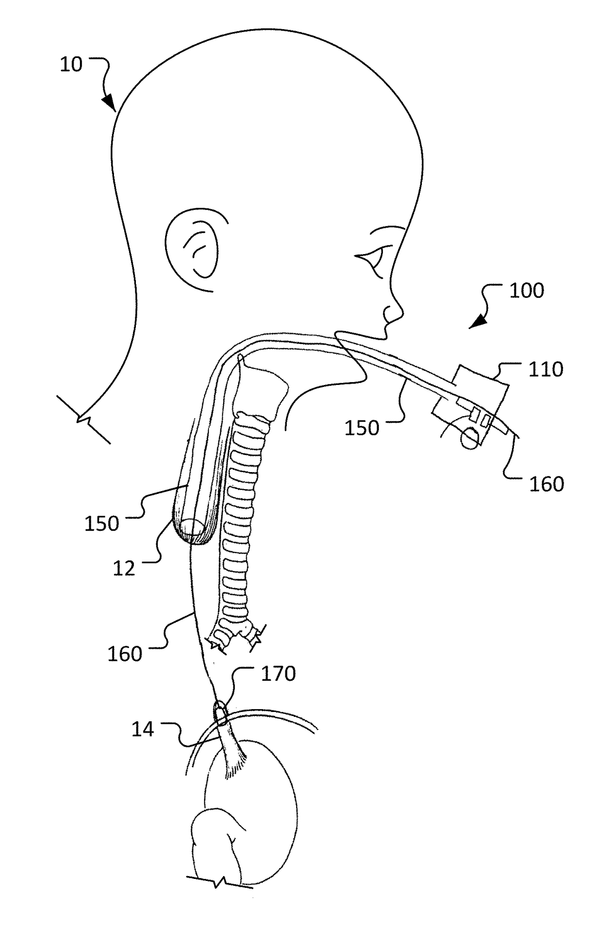
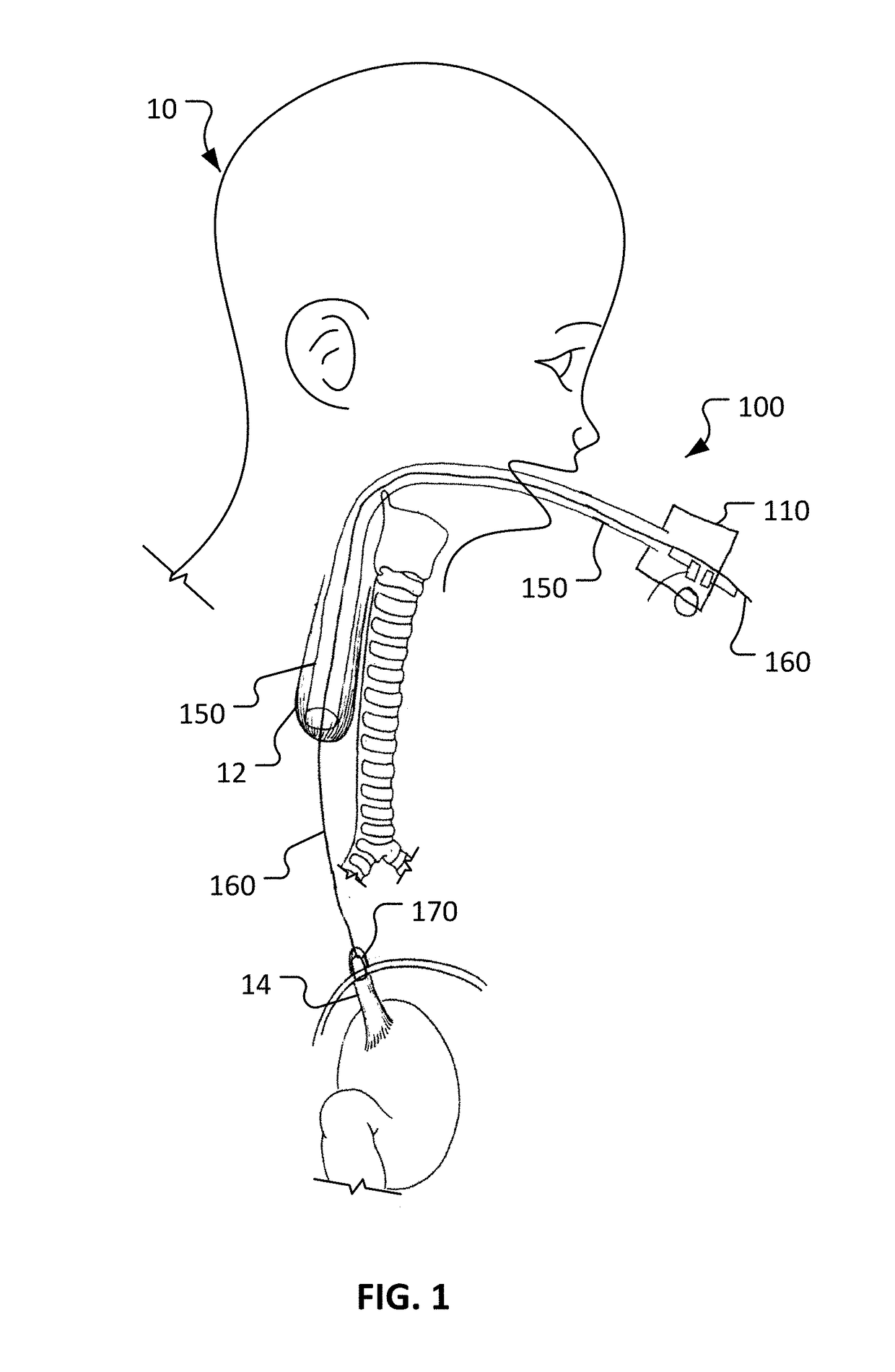
[0024]This disclosure provides devices and methods to treat long gap EA, while obviating much of the delay and complexities associated with current procedures. The devices and methods provided herein involve actively stretching the esophagus portions with traction to promote growth of the esophagus portions. Moreover, the devices and methods provided herein allow for a compression anastomosis to occur between the esophageal ends. This eliminates the need for a second operation to suture the esophageal ends together.
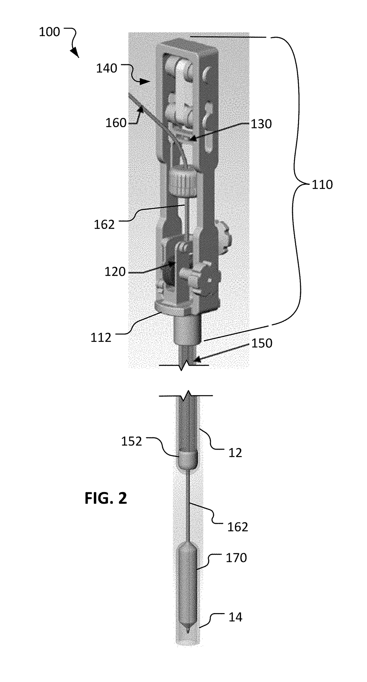
[0025]The anastomotic devices provided herein use an oroesophageal tube that is passed through the baby's mouth to apply pressure on the upper esophageal segment. A balloon tipped catheter is passed via the tube through the upper esophageal segment and into the lower esophageal segment. Once the balloon is inflated and secured, traction is applied between the esophageal ends over a period of several days. Once the esophageal ends have grown together, the balloon and oroes...
PUM
 Abstract
Description
Claims
Application Information
PatSnap Eureka turns technology decisions into work you can execute. Powered by our Innovation Knowledge Graph, it runs expert workflows across engineering, life sciences, materials and intellectual property. Get your review-ready output in minutes.


