Gravure printing plate, gravure printing method, and manufacturing method for electronic component

a technology of gravure printing and electronic components, applied in the direction of fixed capacitors, stacked capacitors, fixed capacitor details, etc., can solve the problems of reducing the productivity of electronic components, and achieve the effect of improving productivity, facilitating the adjustment of printing positions and stacking positions, and improving productivity

Active Publication Date: 2017-11-23
MURATA MFG CO LTD
View PDF1 Cites 3 Cited by
  • Summary
  • Abstract
  • Description
  • Claims
  • Application Information

AI Technical Summary

Benefits of technology

[0016]With the above-described configuration, at least two patterns are able to be printed at one time. This makes it possible to control adjustments to the printing positions and the stacking positions more easily than when two or more patterns are separately printed. The dividing positions of a mother multilayer body are thus able to be adjusted easily. As a result, the productivity is improved.
[0017]According to various preferred embodiments of the present invention, it is possible to provide a gravure printing plate, a gravure printing method, and a manufacturing method for an electronic component that improve productivity.

Problems solved by technology

This decreases the productivity of electronic components.

Method used


Image

  • Gravure printing plate, gravure printing method, and manufacturing method for electronic component
  • Gravure printing plate, gravure printing method, and manufacturing method for electronic component
  • Gravure printing plate, gravure printing method, and manufacturing method for electronic component

Examples


Embodiment Construction

[0029]An electronic component manufactured by using a gravure printing plate according to a preferred embodiment of the present invention will be described below. In this preferred embodiment, a multilayer ceramic capacitor (three-terminal multilayer ceramic capacitor) is used as an example of the electronic component.

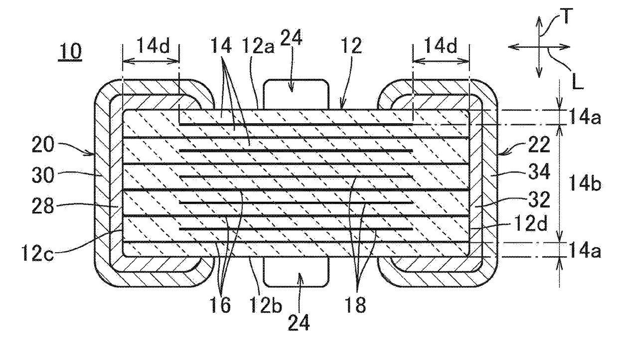
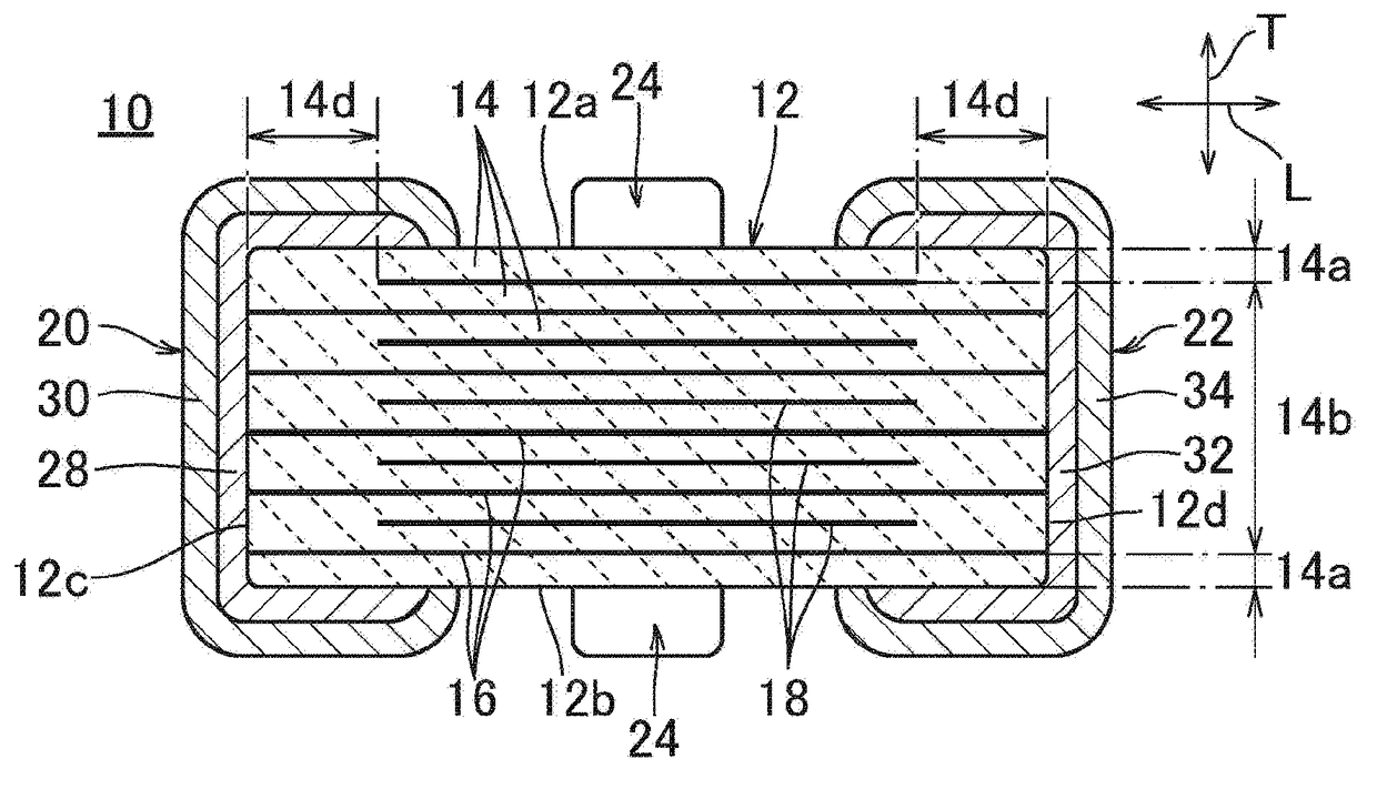
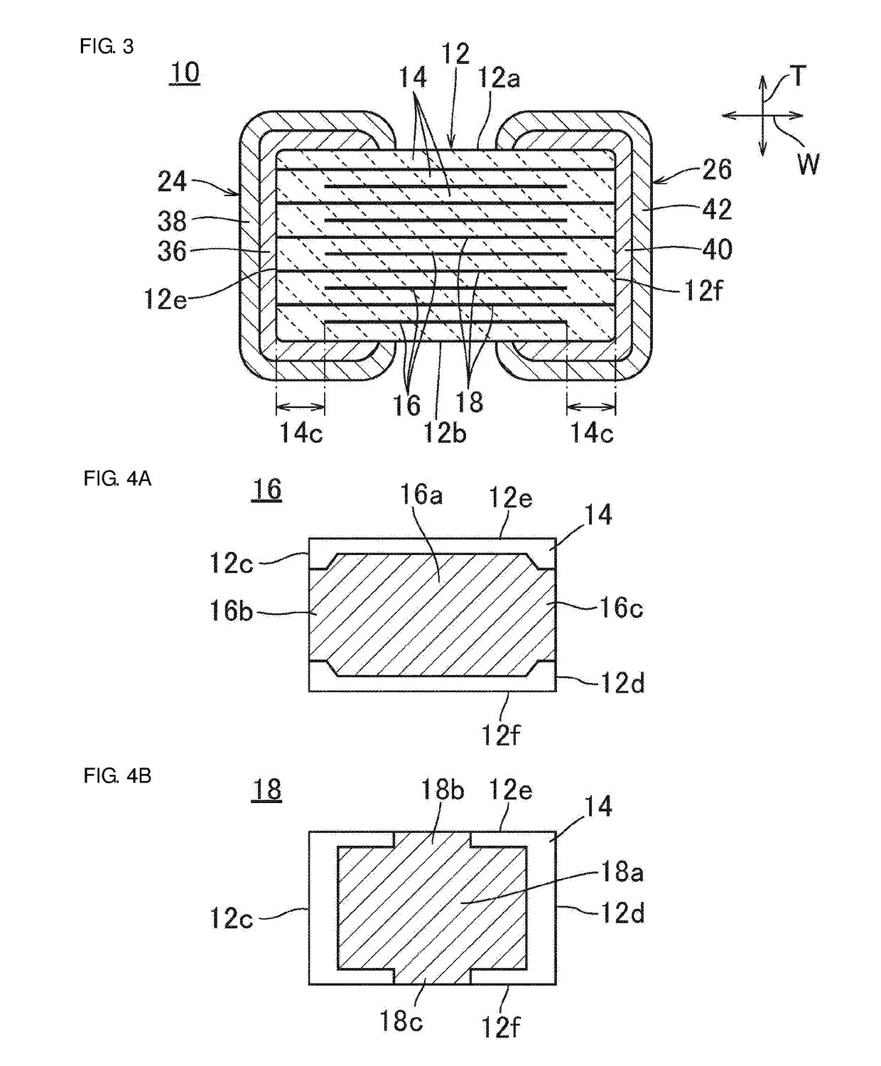
[0030]FIG. 1 is an external perspective view illustrating an example of the configuration of a multilayer ceramic capacitor (three-terminal multilayer ceramic capacitor) 10 manufactured by using a gravure printing plate according to this preferred embodiment. FIG. 2 is a sectional view taken along line II-II in FIG. 1. FIG. 3 is a sectional view taken along line III-III in FIG. 1.

[0031]As shown in FIGS. 1 through 3, the multilayer ceramic capacitor 10 includes a multilayer body 12 preferably with a rectangular or substantially rectangular parallelepiped shape, for example.

[0032]The multilayer body 12 includes plural ceramic layers 14 stacked on each other, plural first...


PUM

PropertyMeasurementUnit
thicknessaaaaaaaaaa
widthaaaaaaaaaa
lengthaaaaaaaaaa

Abstract

A gravure printing plate includes a cylindrical or substantially cylindrical gravure roller with a peripheral surface. Plural cells corresponding to a pattern to be printed are disposed on the peripheral surface of the gravure roller. First and second regions are provided on the peripheral surface of the gravure roller. The pattern to be printed includes at least two patterns. Plural cells corresponding to one of the two patterns are disposed in the first region. Plural cells corresponding to the other one of the two patterns are disposed in the second region.

Description

CROSS REFERENCE TO RELATED APPLICATIONS[0001]This application claims the benefit of priority to Japanese Patent Application No. 2016-100062 filed on May 19, 2016. The entire contents of this application are hereby incorporated herein by reference.BACKGROUND OF THE INVENTION1. Field of the Invention[0002]The present invention relates to a gravure printing plate, a gravure printing method, and a manufacturing method for an electronic component. More specifically, the present invention relates to a gravure printing plate preferably for use in printing an electrode pattern of an electronic component with a paste, a gravure printing method, and a manufacturing method for an electronic component.2. Description of the Related Art[0003]Electronic components, such as multilayer ceramic capacitors, are typically manufactured in the following manufacturing process. Ceramic green sheets on which unfired inner electrode patterns are printed are stacked on each other so as to form a mother multil...

Claims


Application Information

Patent Timeline
Patent Type & Authority Applications(United States)
IPC IPC(8): B41N1/16H01G4/248H01G4/12H01G4/30H01G4/012
CPCB41N1/16H01G4/30H01G4/12H01G4/248H01G4/012H01G4/232B41C1/18B41M1/10B41N1/06H05K3/1275
Inventor SAWADA, TAKASHITOGO, KENICHI
Owner MURATA MFG CO LTD
Why Eureka
Try Eureka