Container for an aerosol generating device

a technology of aerosol generator and container, which is applied in the directions of transportation and packaging, machines/engines, tobacco, etc., can solve the problems of easy damage, bulky and inconvenient, and replaceable parts, etc., and achieves convenient attachment, simplified manufacturing, and more robust container

Active Publication Date: 2017-11-23
JT INT SA
View PDF10 Cites 99 Cited by
  • Summary
  • Abstract
  • Description
  • Claims
  • Application Information

AI Technical Summary

Benefits of technology

[0008]The externally accessible retention means ensures that the modules are easily attachable without any need for disassembly of the container. This in turn reduces the risk of portions of the container being damaged during disassembly and reassembly when modules are changed, allowing for ease of use, a more robust container, and a simplified manufacture.
[0009]Additionally, since the module is not integrally formed with the body, a variety of modules may be interchangeably used with a single body. This enhances usability and adaptability, by allowing the user to add or remove functionality. For example without being limitative, the module may comprise one or more of: one or more replaceable parts for the aerosol generating device, a battery, and a charging device.
[0010]Preferably, the container further comprises one or more readers configured to receive data from a module. Based on this data, a processor of the container may be configured to perform one or more procedures based on the received data. This allows for a “smart container” which constantly monitors various conditions, and allows for the user to more accurate gauge the state of the various devices without themselves inspecting them.
[0011]The processor may be configured to monitor state data, comprising the state of one or more of: the container, the aerosol generating device, the module and articles stored within the module. The processor may also be configured to send a message to a recipient based on the state data and / or the received data. For example, the message may be a request send to a mobile device associated with the user that a particular kind of module should be inserted, or may be an alert that the wrong kind of module has been inserted. This further improves the functionality of the container and provides a significantly safer and more robust user experience.
[0012]Preferably, the body further comprises one or more recesses, each retention means being located in a respective recess. Each retention means is selected from the group consisting of: a slide mechanism; a clip mechanism; and a magnet. Since the retention means are located in a recess, this reduces the risk that the retention means becomes damaged when a module is not inserted, and also provides a clear visual guide to the user as to where the module should be installed. Preferably, the container comprises a cap configured to cover an end of the body, which may be hingedly connected to the body. This allows the contents of the container to be further protected, and can prevent them from falling out of the container when the container is inverted.
[0013]Preferably the body further comprises a second portion configured to receive one or more articles. Where the aerosol generating device comprises at least a permanent part and a replaceable part; the one or more articles may comprise at least one additional replaceable part. This enhances the functionality of the container, by providing for articles associated with the aerosol generating device to be safely and conveniently stored alongside it in a single package.

Problems solved by technology

This means that the replaceable parts, even if they can be included, are susceptible to damage.
This would therefore typically require a user to carry spare replaceable parts and a battery charger, which is bulky and inconvenient.
Accordingly, it remains a problem that there is no convenient and reliable means through which a user can store the permanent part of the aerosol generating device with one or more replaceable parts in order to allow sustained usage of the aerosol generating device over a reasonable period of time, and to provide the aerosol generating device with additional functionality.

Method used


Image

  • Container for an aerosol generating device
  • Container for an aerosol generating device
  • Container for an aerosol generating device

Examples


first embodiment

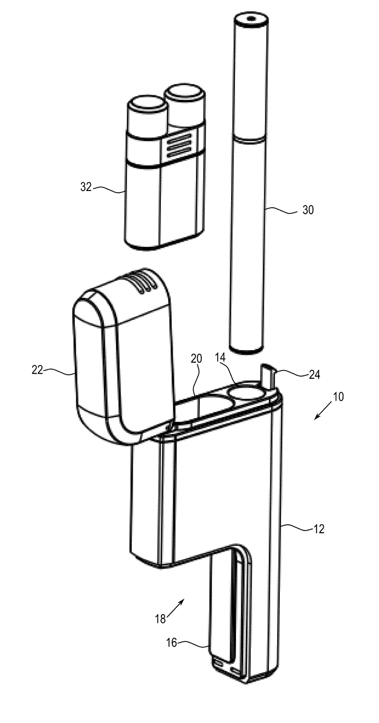
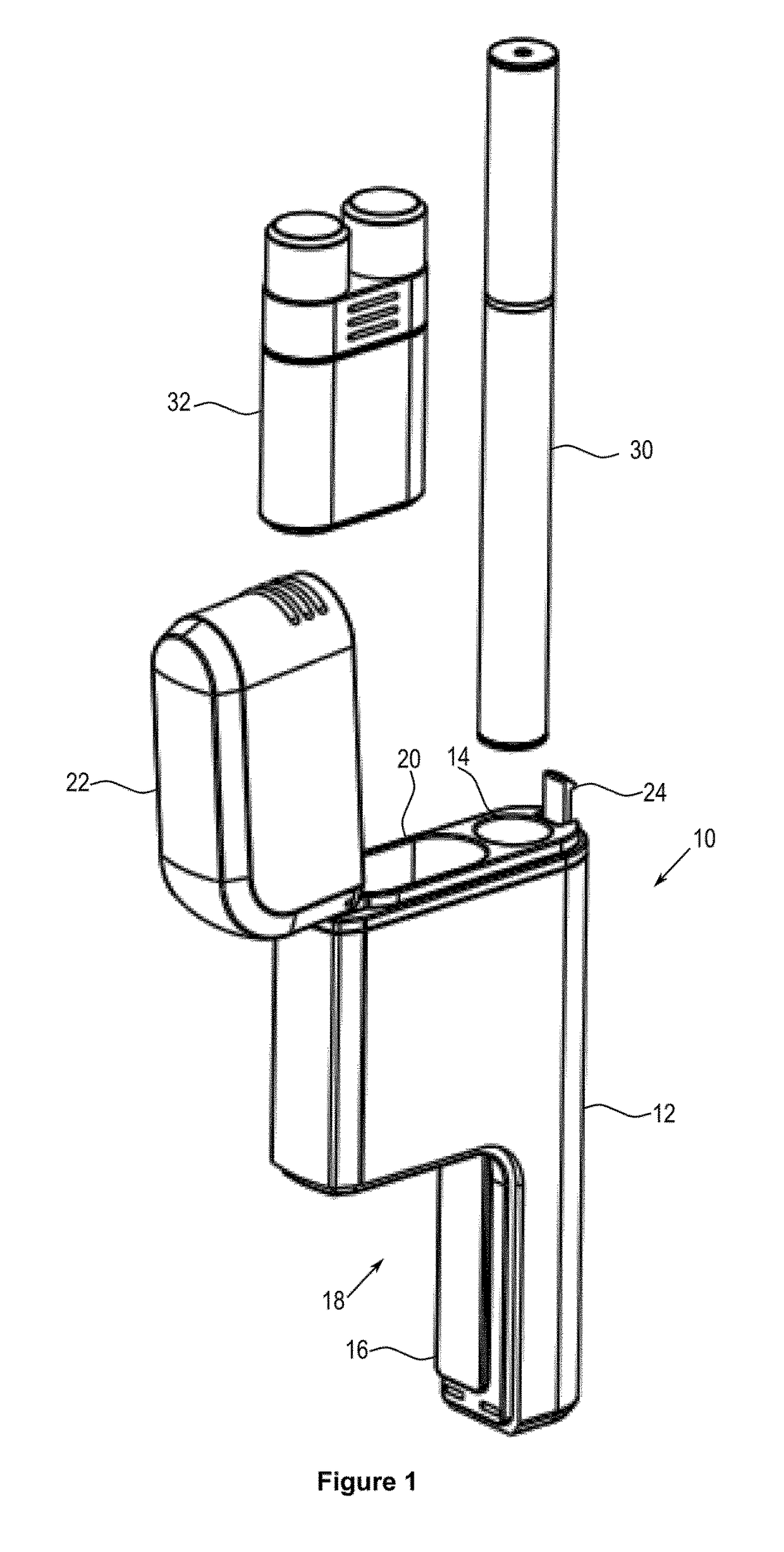
[0046]Turning first to the embodiment shown in FIGS. 1 to 4, the container having an L-shape configuration is shown.

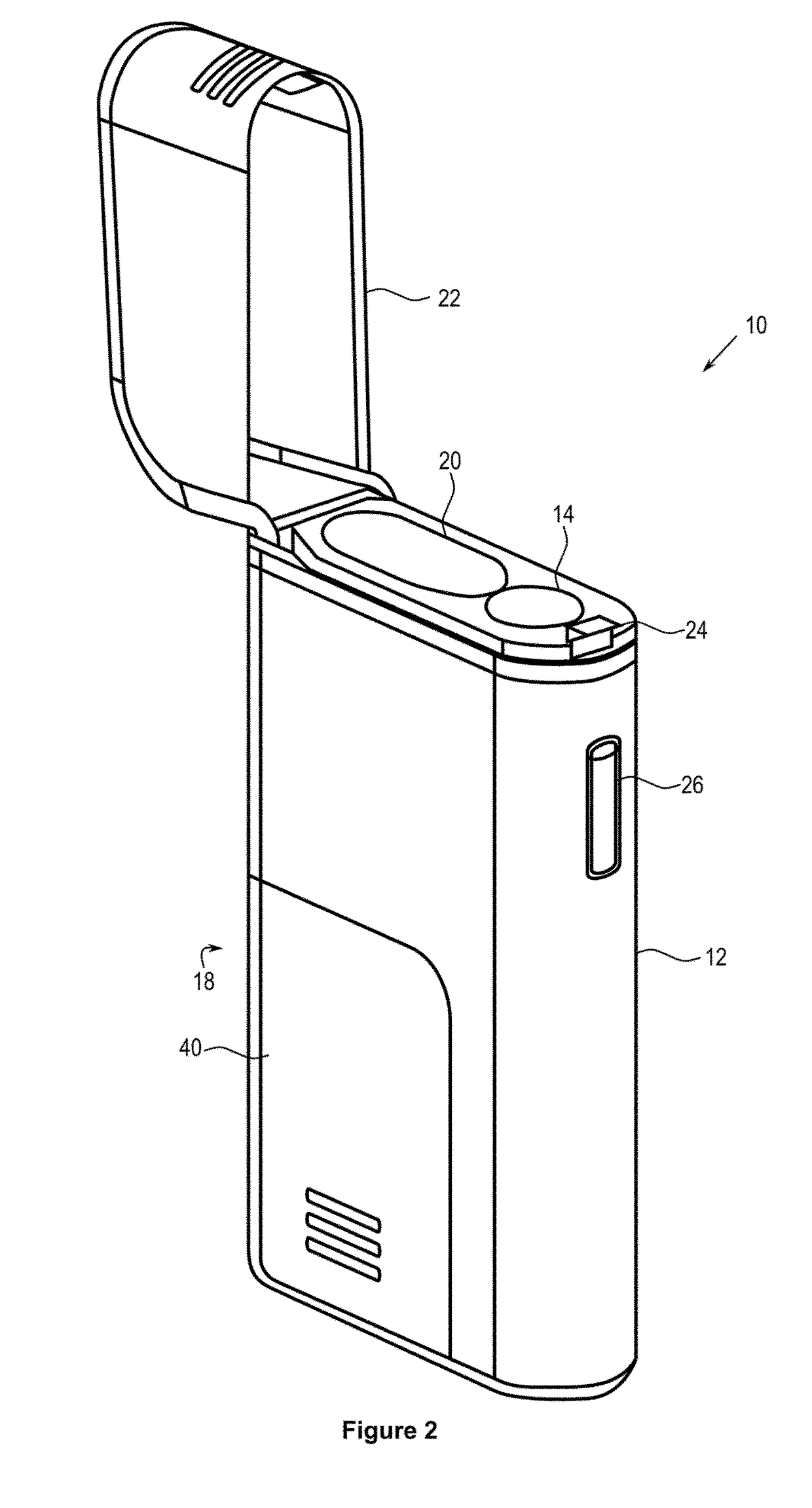
[0047]The container 10 has a body 12 which comprises a first portion 14 for receiving an aerosol generating device 30 (such as an electronic cigarette) and a second portion 20 for receiving one or more additional articles. In this case, the articles comprise two cartridges in a cartridge holder. Each of the cartridges contains a liquid which can be used in the aerosol generating device to generate an aerosol. Once both cartridges are used, the cartridge holder can be reused or disposed of.

[0048]The first portion 14 is formed as a chamber having a first length and a first width, and the second portion 20 is formed as a chamber having a second length and a second width. The chambers are parallel to one another, however the length of the chambers is not equal (that is, the first length is different from the second length). Typically the length of the second chamber is sma...

second embodiment

[0052]FIG. 5 shows the container which has a substantially T-shape configuration.

[0053]The container 10 has a body 12 which comprises a first portion 14 for receiving an aerosol generating device 30 (such as an electronic cigarette) and a second portion 20 for receiving one or more additional articles.

[0054]The first portion 14 is formed as a first chamber having a first length and a first width. The second portion 20 comprises a second chamber having a second length and a second width and a third chamber having a third length and a third width. The second length and the third length are both smaller than the first length. In addition, the second chamber and the third chamber are located on opposite sides of the first chamber.

[0055]Below the second chamber and the third chamber, a first recess and a second recess are respectively provided. Each of the first recess and the second recess is provided with a respective retention means 16 along a respective wall of the recess. Each reten...

third embodiment

[0058]FIG. 6 shows the container, having an I-shaped configuration.

[0059]The container 10 comprises an elongate body 12. At a first end of the body 12, the first portion 14 is provided in the form of a chamber in the body. At a lower end of the body 12, proximate the closed end of the chamber, an externally accessible retention means 16 is provided which is configured to releasably retain a module.

[0060]A recess 18 is formed at a second end of the body. The recess 18 is defined by a top face proximate the closed end of the chamber, and a side face formed by a thin extension of the body 12. The retention means 16 is located in the recess 18. The preferred embodiment shows the retention means 16 on the side face of the recess 18.

[0061]The recess 18 and module 40 are typically configured such that, when the module 40 is installed, the container—module assembly has a substantially I-shape.

[0062]The Cap

[0063]FIGS. 1 to 5 all show embodiments of the present invention where the container 1...


PUM


Abstract

A container for an aerosol generating device is disclosed. The container has a body comprising a first portion configured to receive an aerosol generating device and one or more retention means externally accessible from the body, each retention means being configured to releasably retain a module.

Description

[0001]The present invention relates to a container for holding an aerosol generating device such as an electronic cigarette and one or more modules connectable to the container giving complementary or additional functionality to a user.BACKGROUND[0002]Aerosol generating devices such as electronic cigarettes are relatively well known in the art. In use, a liquid stored in the aerosol generating device is heated to form an aerosol, which is then conveyed to a user. Aerosol generating devices typically involve a permanent part (such as the body of the device) and a replaceable part (such as the cartridge holding the liquid).[0003]While not in use, a user may store the aerosol generating device in a container. Such a container is typically in the form of a box. In some cases, inside the box there is room for one or more of the replaceable parts. These replaceable parts are often simply inserted into the empty space left around the aerosol generating device. This means that the replaceab...

Claims


Application Information

Patent Timeline
Patent Type & Authority Applications(United States)
IPC IPC(8): B65D25/20B65D85/20B65D25/04A24F47/00B65D43/16A24F9/16A24F15/01A24F40/95H02J7/00
CPCB65D25/20A24F9/16A24F47/008H02J7/0042B65D43/16B65D25/04B65D85/20A24F40/95A24F15/01F01N13/1805A24F40/10A24F40/40
Inventor MURPHY, CHRISMAGUIRE, KEVINCARROLL, JAMESROGAN, ANDREWADAIR, KYLE
Owner JT INT SA
Why Eureka
Try Eureka