Exhaust gas analysis system, recording medium recorded with program for exhaust gas analysis system, and exhaust gas analyzing method

a technology of exhaust gas analysis and recording medium, which is applied in the direction of machines/engines, separation processes, instruments, etc., can solve the problems of wasting time required for bag measurement by then, affecting and affecting the quality of exhaust gas analysis, so as to prevent the time spent and improve the efficiency of exhaust gas analysis

Inactive Publication Date: 2017-11-30
HORIBA LTD
View PDF0 Cites 2 Cited by
  • Summary
  • Abstract
  • Description
  • Claims
  • Application Information

AI Technical Summary

Benefits of technology

[0026]According to the present invention configured as described above, the efficiency of exhaust gas analysis can be improved by using an analysis result by the continuous analyzer to prevent the time spent for measuring the exhaust gas introduced into the bag or the filter from being wasted and eliminate the need for steps before the bag measurement.

Problems solved by technology

So-called bag measurement adapted to collect diluted exhaust gas and diluent gas into bags as described above is capable of accurately measuring the concentration of a component, but requires many steps before the measurement, such as calibrating an analyzer in order to measure the diluted exhaust gas and the diluent gas, thus taking a long time to obtain a measurement result.
For this reason, when an obtained measurement result is far out of an assumed range and measurement should be repeated, a time required for bag measurement performed by then goes to waste.
In addition, such a problem may occur not only in the case of the bag measurement but also when exhaust gas is introduced to a filter to measure PM or the like contained in the exhaust gas.
Also, one of causes for taking a long time to obtain a measurement result is the presence of a step of temporarily measuring the diluted exhaust gas in the diluted exhaust gas bag before the bag measurement in order to determine a measurement range used to perform the bag measurement for the diluted exhaust gas bag.
However, in that case, when the concentration of the component in the diluted exhaust gas is different from the assumed one, measurement accuracy may not be ensured.

Method used


Image

  • Exhaust gas analysis system, recording medium recorded with program for exhaust gas analysis system, and exhaust gas analyzing method
  • Exhaust gas analysis system, recording medium recorded with program for exhaust gas analysis system, and exhaust gas analyzing method
  • Exhaust gas analysis system, recording medium recorded with program for exhaust gas analysis system, and exhaust gas analyzing method

Examples


first embodiment

Variations of First Embodiment

[0081]Note that the present invention is not limited to the above-described first embodiment.

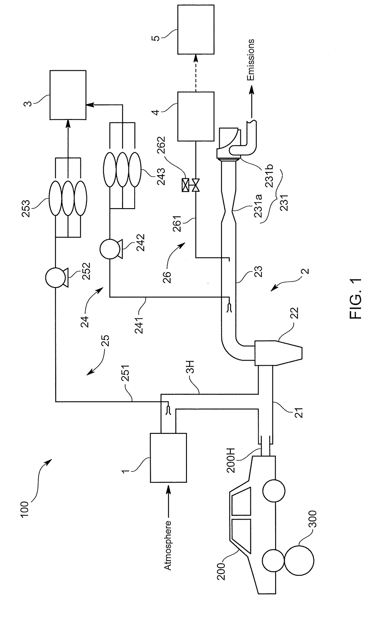
[0082]For example, the above-described embodiment describes the case where, for each of the multiple phases, the diluted exhaust gas and the dilution air are collected into different bags and analyzed. However, the exhaust gas analysis system may be a system adapted to, as prescribed in the 10-15 mode exhaust gas test of TRIAS, run the vehicle in multiple predetermined running modes, and dilute the exhaust gas discharged from the engine over these multiple running modes with the dilution air to collect the diluted exhaust gas into the bags.

[0083]In this case, the predetermined period may be set to a period from the start to completion of the bag collection as in the above-described embodiment, however, it may be configured to set the predetermined period to a period shorter than that period, and before the completion of the bag collection, make the determination...

second embodiment

Variations of Second Embodiment

[0108]Note that the present invention is not limited to the above-described second embodiment.

[0109]For example, the calculation part in the above-described embodiment is one adapted to calculate the average concentrations of the predetermined components during the predetermined period, but may be one adapted to calculate the integrated values of the predetermined components during the predetermined period.

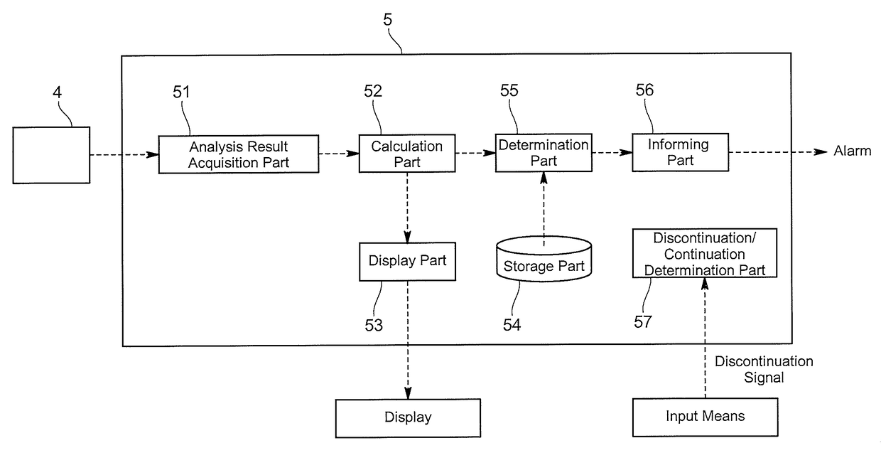
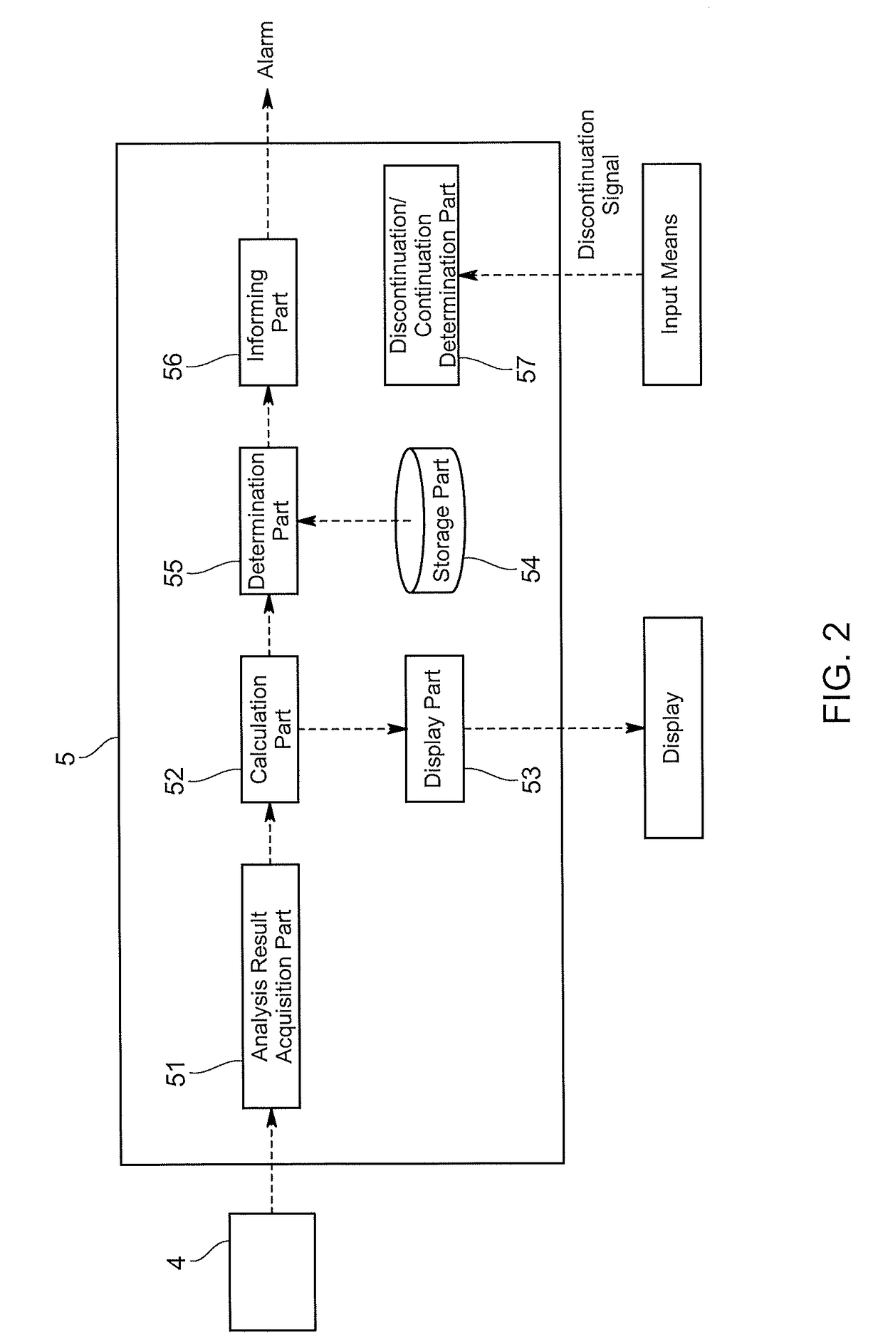
[0110]Also, as in the first embodiment, the information processing unit may include a display part adapted to output calculation results calculated by the calculation part for display on a display or the like.

[0111]In doing so, independently of a determination result by the determination part, a user can determine measurement ranges used for bag measurement on the basis of values displayed by the display part.

[0112]The present invention is not limited to any of the above-described embodiments and variations.

[0113]For example, the information processi...


PUM

PropertyMeasurementUnit
concentrationaaaaaaaaaa
flow rateaaaaaaaaaa
timeaaaaaaaaaa

Abstract

An exhaust gas analysis system is adapted to include an exhaust gas circulation line through which exhaust gas flows, an exhaust gas collection line adapted to collect the exhaust gas from the exhaust gas circulation line and introduce the collected exhaust gas into an exhaust gas analysis device, a continuous analysis line adapted to, separately from the diluted exhaust gas collection line, collect the exhaust gas from the exhaust gas circulation line for continuous analysis, a continuous analyzer provided in the continuous analysis line, and an information processing unit adapted to, on the basis of an analysis result by the continuous analyzer at the time of the collection into the exhaust gas analysis device, determine whether a measurement result of the exhaust gas introduced into the exhaust gas analysis device falls within a preset range, or determine a measurement range used to measure the exhaust gas introduced into the exhaust gas analysis device.

Description

TECHNICAL FIELD[0001]The present invention relates to an exhaust gas analysis system adapted to analyze, for example, exhaust gas discharged from an engine, a recording medium recorded with a program for the exhaust gas analysis system, and an exhaust gas analyzing method.BACKGROUND ART[0002]As an exhaust gas analysis system, as disclosed in Patent Literature 1, there has been one using a constant volume sampling apparatus that is configured to sample the total amount of exhaust gas discharged from an internal combustion engine, dilute the totally sampled exhaust gas with diluent gas to produce diluted exhaust gas, and control the flow rate of the diluted exhaust gas to be constant.[0003]Specifically, this system calculates the concentration of a component in the exhaust gas by collecting the diluted exhaust gas into a diluted exhaust gas bag as well as collecting the diluent gas into a diluent gas bag, and subtracting the concentration of the component in the diluent gas in the dil...

Claims


Application Information

Patent Timeline
Patent Type & Authority Applications(United States)
IPC IPC(8): G01N15/06G01M15/10F01N3/021B01D46/44G01N15/00
CPCG01N15/0618F01N3/021B01D2279/30B01D46/442G01N2015/0046G01M15/102G01N1/34G01N1/38G01N33/0032G01N2001/2255G01M15/02G01N1/2252
Inventor TOKUHIRA, MASATSUNEOKADA, JUNGOHIGUCHI, MASAHIRO
Owner HORIBA LTD
Why Eureka
Try Eureka