Electric connector and battery comprising the same

a technology of electric connectors and batteries, applied in the field of batteries, can solve the problems of high cost of local thinning and twisting process of electric connectors, affect welding quality, complex structure of thinned and twisted portions, etc., and achieve safe and credible performance, avoid damage to tabs, and reduce costs

Inactive Publication Date: 2017-11-30
BYD CO LTD
View PDF16 Cites 2 Cited by
  • Summary
  • Abstract
  • Description
  • Claims
  • Application Information

AI Technical Summary

Benefits of technology

[0005]Accordingly, an electric connector is provided by the present disclosure and has a plurality of advantages, such as a convenience of welding, a simple structure, a lower process cost, a stable and reliable structure, a high security and so on.
[0008]The electric connector according to embodiments of the present disclosure has a plurality of advantages, such as a convenience of welding, a simple structure, a lower process cost, a stable and credible structure, a high security and so on.
[0027]The battery according to the present disclosure shows a plurality of advantages, such as a convenience of manufacturing, a lower cost, a safe and credible performance and so on.
[0028]The connecting sheets welded to tabs and the leading-out sheet are separate parts, so the connecting sheets may be welded to the tabs at first, then the leading-out sheet may be welded to the connecting sheets, which may guarantee that a welding head does not interfere with adjacent tabs during a welding process, thus facilitating welding and avoiding damages to tabs.

Problems solved by technology

During the process of ultrasonic welding, a welding head may occupy a large space, which may cause interference with adjacent tabs while the plurality of winding cores is provided.
Thus the welding between the electric connector and the tabs may be inconvenient, which may affect welding quality.
Moreover, the cost of the local thinning and twisting process of the electric connector is very high, and the thinned and twisted portion has a complex structure, concentrative stress, poor flow capacity and high current density.
In other words, the electric connector shows not only poor structure stability, but also a high temperature during high-rate charge / discharge, which may destroy the stability of a system and cause a security problem.

Method used


Image

  • Electric connector and battery comprising the same
  • Electric connector and battery comprising the same
  • Electric connector and battery comprising the same

Examples


Embodiment Construction

[0040]Reference will be made in detail to embodiments of the present disclosure, where the same or similar elements and the elements having the same or similar functions are denoted by like reference numerals throughout the descriptions. The embodiments described herein with reference to drawings are explanatory, illustrative, and used to generally understand the present disclosure. The embodiments shall not be construed to limit the present disclosure.

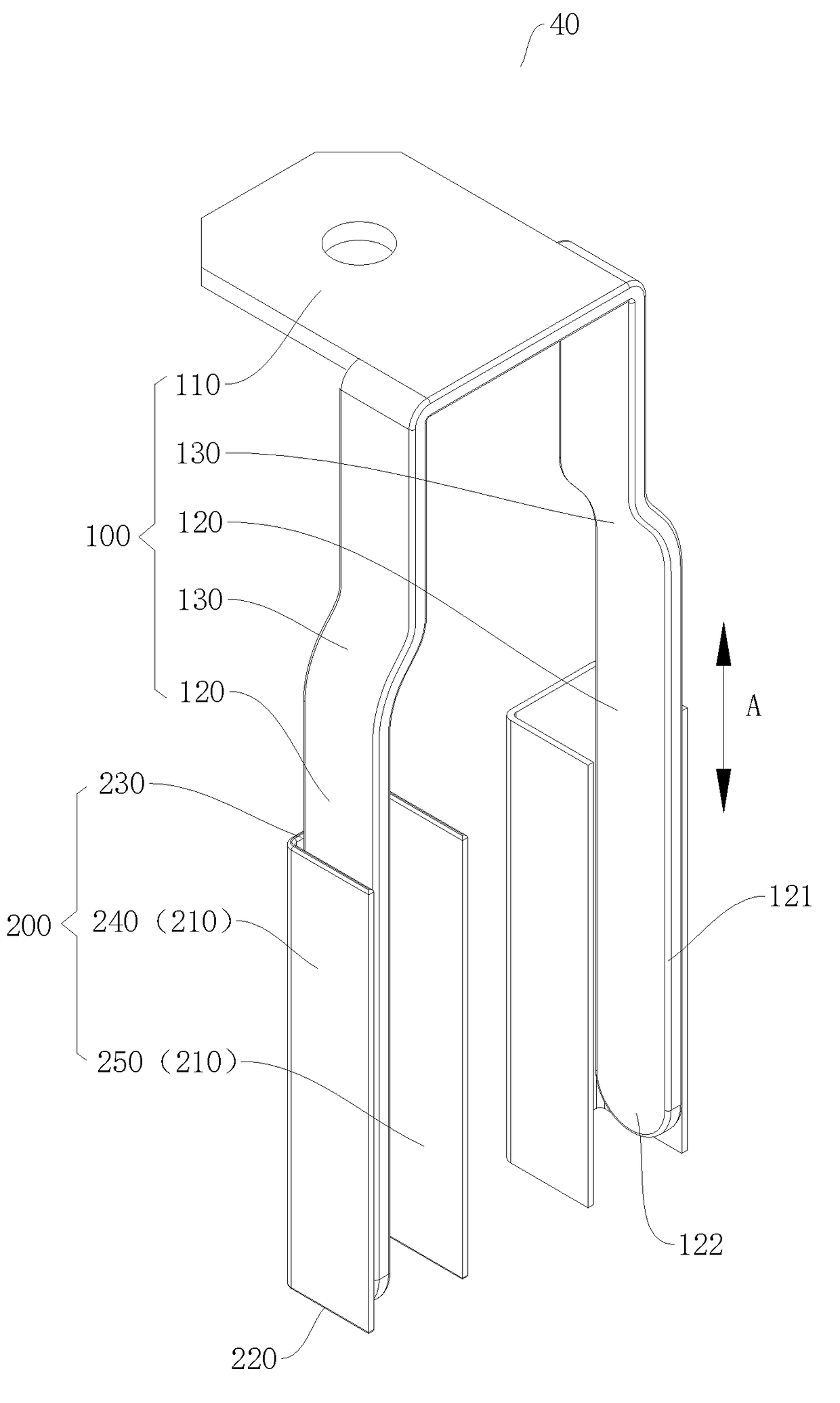
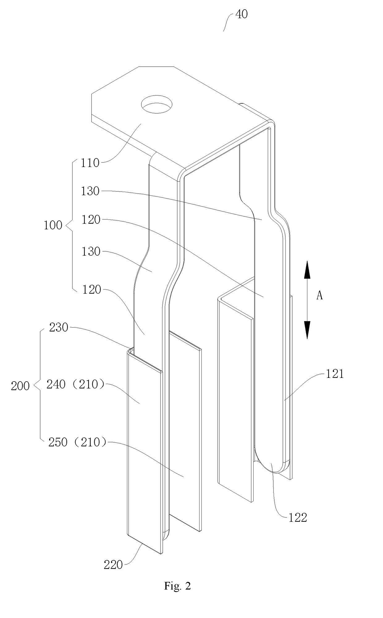
[0041]An electric connector 40 according to embodiments of the present disclosure will be described with reference to drawings below.

[0042]As shown in FIGS. 2 to 4, the electric connector 40 includes a leading-out sheet 100 and a plurality of connecting sheets 200.

[0043]The plurality of connecting sheets 200 are welded to the leading-out sheet 100, and the leading-out sheet and the plurality of connecting sheets are separate parts, i.e. the electric connector is not an integrated piece. Each connecting sheet 200 includes at least two ...


PUM

PropertyMeasurementUnit
thicknessaaaaaaaaaa
current densityaaaaaaaaaa
structure stabilityaaaaaaaaaa

Abstract

The present disclosure discloses an electric connector and a battery comprising the same. The electric connector includes a leading-out sheet, and a plurality of connecting sheets welded to the leading-out sheet, each connecting sheet comprising at least two welding portions; wherein the leading-out sheet and each connecting sheet are separate parts. The electric connector according to the present disclosure is convenient in welding, simple in structure, low in process cost, stable and reliable in structure and high in safety.

Description

CROSS-REFERENCE TO RELATED APPLICATION[0001]This application is a continuation application of International Application No. PCT / CN2016 / 077994, filed on Mar. 31, 2016, which is based on and claims priority to and benefits of Chinese Patent Application No. 201520188443.8, filed with the State Intellectual Property Office (SIPO) of the People's Republic of China on Mar. 31, 2015. The entire contents of the above-identified applications are incorporated herein by reference.TECHNICAL FIELD[0002]The present disclosure relates to the field of battery, and more particularly relates to an electric connector and a battery comprising the same.BACKGROUND[0003]In the related art, in a battery including a plurality of winding cores, an electrode terminal of a cover plate is connected to tabs of the winding cores via an electric connector. The electric connector is integrally formed and locally thinned and twisted to form a plurality of welding portions, as shown in FIG. 1. The welding portions ar...

Claims


Application Information

Patent Timeline
Patent Type & Authority Applications(United States)
IPC IPC(8): H01M2/26H01M2/04H01M2/34H01M2/24H01R11/28H01M10/0525H01M50/502H01M50/529H01M50/533H01M50/536H01M50/538
CPCH01M2/263H01M2/34H01M2/24H01M10/0525H01M2/0426H01M2200/10H01R11/28Y02E60/10H01M50/538H01M50/536H01M50/533H01R11/281B23K2101/38H01M50/169H01M50/529
Inventor JIANG, LUXIAYANG, KELIZHU, YANZHU, JIANHUA
Owner BYD CO LTD
Why Eureka
Try Eureka