In-vehicle unit and in-vehicle unit diagnosis system

a technology for in-vehicle units and diagnostic systems, which is applied in the direction of registering/indicating vehicles, instruments, and vehicle registration/indicating, etc., can solve the problems of difficulty in specifying the operation tendency of various sensors, in-vehicle units may not be able to appropriately obtain the service provided, etc., and achieves the effect of increasing labor hours and increasing costs

Active Publication Date: 2017-12-07
DENSO CORP
View PDF0 Cites 22 Cited by
  • Summary
  • Abstract
  • Description
  • Claims
  • Application Information

AI Technical Summary

Benefits of technology

[0017]The in-vehicle unit may be able to acquire information about an exterior environment that influences the sensor operational situation. In such a case, the use of a threshold value corresponding to the exterior environment can determine whether the sensor operates normally.
[0018]However, acquisition of the information to indicate the exterior environment requires separately adding a specific configuration to the in-vehicle unit, thus increasing costs. A threshold value to determine whether the operation is normal or abnormal needs to be specified correspondingly to each of estimated exterior environments, thus increasing labor hours for the software design. Even a normal operation may be incorrectly determined to be abnormal when the host vehicle travels under an unexpected environment.

Problems solved by technology

The in-vehicle unit may not be able to appropriately obtain the service provided from the service provider terminal.
However, it is difficult to specify the operation tendency of various sensors (such as the acceleration sensor) used for the in-vehicle unit because an exterior environment to use the in-vehicle unit varies dynamically.

Method used


Image

  • In-vehicle unit and in-vehicle unit diagnosis system
  • In-vehicle unit and in-vehicle unit diagnosis system
  • In-vehicle unit and in-vehicle unit diagnosis system

Examples


first modification

[0172]As above, any of the in-vehicle units 1 in the in-vehicle unit diagnosis system 100 has the same function but is not limited thereto. Different functions may be provided for the in-vehicle unit 1 to be diagnosed and the diagnosing in-vehicle unit 1.

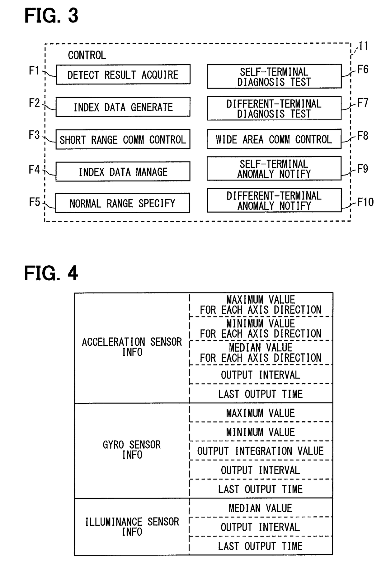
[0173]The in-vehicle unit 1 to be diagnosed just needs to include at least the detection result acquisition section F1, the index data generation section F2, and the short range communication control section F3 having the function to transmit the index data-item of the self terminal.

[0174]The diagnosing in-vehicle unit 1 just needs to include at least the short range communication control section F3 having the function to acquire the index data-item transmitted from the in-vehicle unit 1 to be diagnosed, the index data management section F4, the normal range specification section F5, the different-terminal diagnosis test section F7, and the wide area communication control section F8.

[0175]According to the above-mentioned configurati...

second modification

[0177]The case where the sensor provided for the in-vehicle unit 1 does not operate normally may include a case where the in-vehicle unit 1 is not attached to the vehicle in accordance with a correct posture. The correct posture signifies a predetermined attachment posture.

[0178]The self-terminal diagnosis test section F6 may therefore determine whether the attachment posture of the self terminal is correct. The different-terminal diagnosis test section F7 may determine whether the in-vehicle unit 1Bb as a diagnosis target is attached to a vehicle Bb mounted with the in-vehicle unit 1Bb according to the correct posture.

[0179]As an example, the description below illustrates a mode in which the self-terminal diagnosis test section F6 of the in-vehicle unit 1A determines whether the attachment posture of the self terminal is correct, based on detection values output from the acceleration sensor 15 in the three axis directions.

[0180]The description below first explains the relationship ...

third modification

[0200]The second modification illustrates the mode in which each in-vehicle unit 1 includes the GNSS receiver 14 and the stopping determiner section F11 and uses a result detected by the acceleration sensor 15 while the vehicle stops to determine whether the in-vehicle unit 1 is attached according to the correct attachment posture. However, the mode is not limited thereto.

[0201]The in-vehicle unit 1 may not include the GNSS receiver 14 and the stopping determiner section F11 and use a median in the index data-item for the acceleration sensor 15 in each axis direction to determine whether the attachment posture of the self terminal or the nearby in-vehicle unit 1B is correct in relation to the vehicle. The description below illustrates a mode in which the self-terminal diagnosis test section F6 of the in-vehicle unit 1A determines whether the attachment posture of the self terminal is correct.

[0202]As described in the second modification, no force is generated to act on the in-vehicl...


PUM


Abstract

An in-vehicle unit used in each of host vehicles including a subject vehicle and nearby vehicles communicates information using inter-vehicle communication, generates an index data-item including an index value indicating an operational situation of a sensor instrument based on a detection result from the sensor instrument, and transmits the generated index data-item via the wireless communicator. A subject in-vehicle unit used in the subject vehicle includes: a communication processing section that acquires the index data-item from nearby in-vehicle units; a determination criterion specification section successively specifies a different-unit determination criterion based on the acquired index data-item; and a different-unit diagnosis test section that determines whether a sensor instrument in a target nearby in-vehicle unit operates normally, by comparing the different-unit determination criterion with the index data-item acquired from the target nearby in-vehicle unit.

Description

CROSS REFERENCE TO RELATED APPLICATION[0001]The present application is based on Japanese Patent Application No. 2015-3462 filed on Jan. 9, 2015, the disclosure of which is incorporated herein by reference.TECHNICAL FIELD[0002]The present disclosure relates to an in-vehicle unit and an in-vehicle unit diagnosis system that diagnose whether an in-vehicle unit itself or other nearby in-vehicle units normally operate.BACKGROUND ART[0003]Recently, there is proposed a system in which an in-vehicle unit mounted on each of a plurality of vehicles (referred to as host vehicles) wirelessly communicates with other in-vehicle units existing within a predetermined range from the in-vehicle unit itself without using a wide area communication network. This type of communication between in-vehicle units is generally referred to as an inter-vehicle communication.[0004]This type of in-vehicle unit includes a positioning radio wave receiver and a sensor. The positioning radio wave receiver such as a G...

Claims


Application Information

Patent Timeline
Patent Type & Authority Applications(United States)
IPC IPC(8): G07C5/00G07C5/08H04L29/08
CPCG07C5/008H04L67/12G07C5/0816G07C5/0825
Inventor KUMABE, SEIGOU
Owner DENSO CORP
Why Eureka
Try Eureka